-
Notifications
You must be signed in to change notification settings - Fork 3
Case Studies
On the science station I designed for the 2019 rover in Husky Robotics, I needed to have 4 PWM outputs running at 20KHz out of a Raspberry Pi. Sadly, the Pi does not have 4 outputs, and other devices such as the PCA9685 can not go up to anywhere near 20KHz. I looked around for a long time to try and find other dedicated PWM generator ICs, but was not able to find anything reasonably priced that did what I needed.
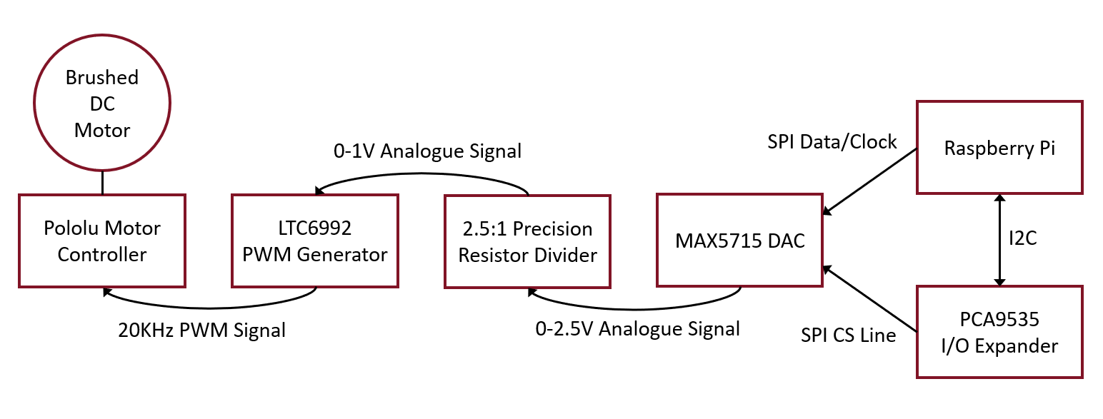
In order to solve this problem, I ended up choosing a somewhat complex chain of components that would generate exactly the signals I needed, and implementing this in software was quite simple thanks to Scarlet's I/O systems. First, an explanation of how the signals were created. I decided on using the LTC6992. This would take in an analogue signal between 0V and 1V, and output a corresponding PWM signal, at a frequency decided by resistors. Since the Pi does not have any analogue outputs, I used a MAX5715 DAC, which created a 0-2.5V analogue signal that was put through a precision 2.5:1 resistor divider to get the desired range, while maintaining the high resolution of the DAC. The DAC was connected to the Pi via SPI, and to drive the CS line, I needed to connect it to an I/O expander, the PCA9535, as all other GPIO pins on the Pi were in use by other system components.
Scarlet's device and I/O systems not only make implementing this straightforward and logical, but also keeps all of the parts re-usable, so that anyone else using any of these components in any combination can use our existing work without needing to do additional work at all.
This first diagram shows how the components are actually connected in hardware:
And this diagram shows how the components are used and connected in software:
One of the goals of Scarlet's I/O system is that the software mimics the hardware, as you can see by the similarities above. This means software developers can get back to writing the code that actually makes a system operate, rather than worrying about how to implement and talk to hardware. All you need is a specification of how the hardware is connected, then simply replicate that structure in software to make it work. Not to mention, like all other Scarlet I/O, it is trivial to port to other platforms like the BeagleBone Black.
Here's the code that makes this work, you'll notice a pattern similar to the above diagrams:
// Basic I/O
II2CBus I2C = new I2CBusPi();
ISPIBus SPI = new SPIBusPi(0);

// I/O Expander
PCA9535E IOExpander = new PCA9535E(I2C, 0x27);
IOExpander.SetChannelMode(4, true); // Setting to output mode.
IDigitalOut CS_DAC = IOExpander.Outputs[4];
CS_DAC.SetOutput(true);

// DAC
MAX571x DAC = new MAX571x(SPI, CS_DAC, MAX571x.Resolution.BitCount12, MAX571x.VoltageReferenceMode.Reference2V500);
IAnalogueOut DACOut = DAC.Outputs[0];

// Resistor Divider
AnalogueOutTransform ResistorDiv = new AnalogueOutTransform(DACOut, (range => range / 2.5), (val => val * 2.5));

// Analogue-to-PWM
LTC6992 PWMOut = new LTC6992(ResistorDiv);

// Motor Controller
IDigitalOut MotorDir = IOExpander.Outputs[8];
PololuHPMDG2 MotorCtrl = new PololuHPMDG2(PWMOut, MotorDir, 0.99F);
MotorCtrl.SetEnabled(Enable);
MotorCtrl.SetSpeed(0.2F);
Quick Links:
NuGet
Pin Diagrams: RPi | BBB
Developers: CaiB, Baldstrom
General Info:
Home
Common Issues
Getting Started
Supported Devices
Sections:
Logging
DataLog
Filters
Hardware I/O:
- BeagleBone Black
- Raspberry Pi
- Pin Diagrams: RPi | BBB
- GPIO: Using | For Beginners
- PWM: Using | For Beginners
- ADC: Using | For Beginners
- I2C: Using | For Beginners
- SPI: Using | For Beginners
- UART: Using | For Beginners
- CAN: Using | For Beginners
Networking
Sensors
StateStore
Other: Interesting Case Studies

