-
Notifications
You must be signed in to change notification settings - Fork 3
RFID Moisture Updates
post newest updates at the top and have dividing lines between them:
Author: Matt Guo
- A Redesign in the RFID mount has been completed and attempted to implement on the Irrigation boom. Another Redesign is needed for the mechanical system.
Show More
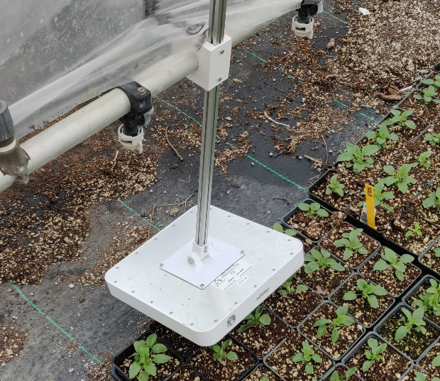
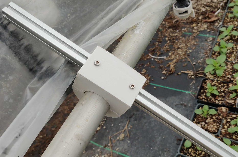
DescriptionA redesign in the irrigation boom to RFID antenna hardware was done to provide greater support to the structure. By adding more width to the overall 3D printed piece, the mechanical structure should be able to support the weight of the antenna with the added pressure from the plastic sheet.
The tolerance of the 3D printed piece had been adjusted prior to the redesign to relieve the tension off of the screws. This adjustment in the tolerance was too much, and left no clamping force into the irrigation boom. A new piece is needed for implementation.
What's Next:
- The tolerance on the piece to mount onto the 1 inch rail needs to be investigated.
- The addition of a rubber or pliable material to limit the contact of metal to plastic connection may be needed for additional friction.
Author: Matt Guo
- Went to Peoria Gardens to check on the RFID Antenna mount, found a flaw in the design, and will work on a mechanical fix.
Show More
DescriptionIn early April, we received an email from Nico Aidans at Peoria Gardens that stated the antenna mount on the irrigation boom needed tweaking. It seemed that the RFID Antenna mount is prone to getting caught on the plastic sheet mechanically controlled on the irrigation boom. This plastic sheet is often used to shunt the growth of certain plants, which can get caught by the RFID Antenna mount.
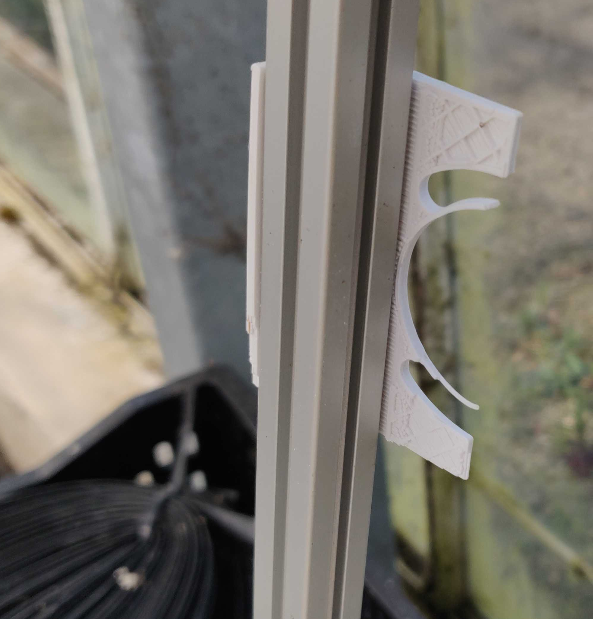
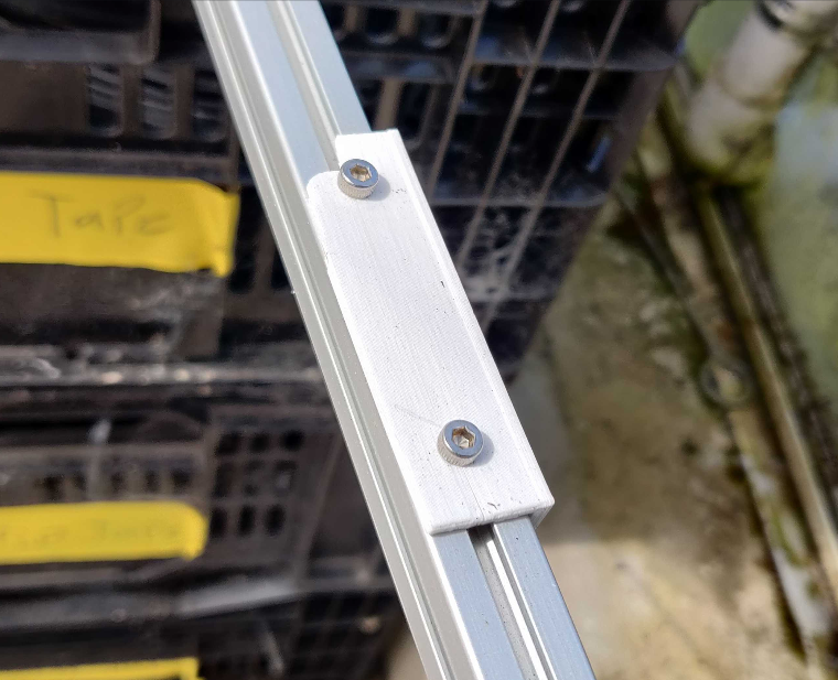
The stress of dragging the plastic sheet caused the RFID Antenna to snap from the irrigation boom, showing us the weakest point of the irrigation mount. The images below show the weakest point of the irrigation setup:

What's Next:
- A redesign in the antenna to irrigation rail piece is currently being redesigned by adding the support structure larger.
Author: Matt Guo
- Created RevA on State Machine implementation on RFID irrigation code, awaiting proper threshold macros from calibrated data.
Show More
DescriptionThe RFID irrigation State Machine code is implemented in black box format on the calibration procedure of the RFID tags for added mobility in the timeline of the project, ensuring that the irrigation State Machine code is not halted by any progress on the RFID calibration. Essentially, the implementation of the irrigation State Machine should be such that it only accepted two calibration points from the RFID calibration procedure: a low threshold number and a high threshold number. Everything else can be abstracted out.

These macros for the low threshold and high threshold contains the proper controls for the implemented state machine, and are the only input unknown interfaces for this code, at of this current date.
The template of the code still contains foundations of constant read implementation for the Feather M0, which was also taken from the Sparkfun RFID Constant Read example from the library. The biggest changes, of course, is the added implementation of the State Machine and the tag objects embedded to the program.
The data on each tag is abstracted and grouped into tag structs, defined globally in the program:

These contain the last moisture value retrieved, RSSI, threshold, current state, etc. The motivation behind doing this way is that each tag done can have a separate State Machine for added robustness on the overall implementation; rather than constantly having to infer that each tag will share the same state, they can all be separated into different states for a more precise irrigation system, with the cost of added computation and complexity.
The tag objects are stored in a global tag object array of a known size, which is set in the macro at the beginning of the program. The true size of this will be determined at implementation launch, once we are sure of the quantity of needed tags.

An initial sweep of the program is needed to read all of the tags and store them in the array. The EPC information, previous moisture value, RSSI, etc are all stored in this array of tag objects. Once the system identifies a new tag based off of a new EPC, then it will store that new tag object into the array.


If the system finds a tag that so happens to already reside in the global array of tag objects, it will update the parameters of that object and then proceed to implement the State Machine of that identified tag.

The State Machine contains three important states: a threshold comparison state, a wet cycle state, and a dry cycle state. At the comparison state, the identified tags stored threshold rating (max or min) is checked. If the tag contains a low threshold rating, then that means that specific plant is on the wet cycle, and the state is changed to the wet cycle state. If the tag contains a high threshold rating, then that means that specific plant is on the dry cycle, and the state is changed to the dry cycle state. At the wet cycle, the plant is continuously watered until the moisture value is at or below that threshold rating. Once this happens, then the tag will revert to a high threshold rating so that the next pass can be a dry state. For the dry cycle, the RFID will monitor the current moisture of the tag to see if it has hit the dry threshold. If the current moisture value has not quite reached that dry threshold, then it means that the plant is still considered to be a bit wet, thus will keep drying that plant. Once the plant is sufficiently dry, i.e. the current moisture value is as high or higher than the high threshold value, then the state will be triggered to a wet cycle. This creates the needed oscillation for the plants that Peoria Gardens wants.


What's Next:
- An overall Fertigate state is needed for this implementation, which can be done by pulling the second EPC hex data for each individual tag to see if they are a part of the fertigate pass or not. This state cannot be individualized for each tag object, but must be for the overarching system.
- The current implementation for the relay watering is to turn on for a specified amount of time before needing to turn off for the next reading loop. Ideally, this would be continuous until it reaches a tag or a moisture value that designates a turn off. This should be implemented next.
Author: Matt Guo
- Max and I successfully deployed the RFID hardware to the irrigation boom at Peoria Gardens after some slight mechanical changes to the antenna mount.
Show More
DescriptionThe second attempt at the deployment of the RFID setup went successfully at Peoria Gardens, one week after the initial attempt. We noticed during the first attempt that the antenna was mounted too far away from the RFID tags embedded in the soils of the Pansy crops that we were collecting data from. Due to this, the antenna had a difficult time picking up the signals of the RFID tags. Thus, for the second attempt, a new mechanical design was created to bring the antenna closer to the Pansy soil. The setup looked like this:

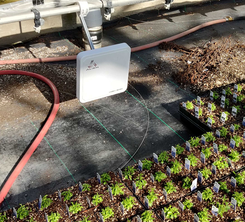
The tags were embedded so that they faced parallel with the face of the antenna for maximum and more reliable readability for the RFID hardware. We noticed through testing that if the tags were parallel to the face of the antenna, we would get a stronger RSSI signal.

The pelican case with the onboard electronics is situated in the same place as the initial deployment, on the side rail of the irrigation boom. The orientation of the pelican case was done in a way so that a debug light is pointed up for quick check on whether the tags are being read.

On the slowest speed of the irrigation boom, the tags were being read when swept through the crops. This setup will be in Peoria for the next couple of weeks as we collect RFID moisture data from the plants.
Author: Matt Guo
- Max and I attempted to deploy the RFID Reader to Peoria Gardens to log RFID tag data, but was unsuccessful. Second deployment attempt scheduled for Feb 25 2020.
Show More
DescriptionThe first attempt to deploy the RFID Reader to Peoria Gardens was unsuccessful. The irrigation boom was too far away for the RFID antenna to read the RFID tags appropriately. The mounting of the control box and the RFID tags are as follows:
The control box:

The control box contains the onboard electronics, such as the Feather M0, Hypnos Board, the RFID SparkFun Reader, and the interface board. It includes a light in the form of a NeoPixel for debugging purposes.
The antenna:

The problems with this first attempted deployment was the antenna distance from the RFID tags, which were planted in the Pansy crops. Due to the vertical orientation of the RFID tags in such crops, depicted below, the angle of attack of the beam reading for the RFID antenna was not optimized.
The RFID tags:

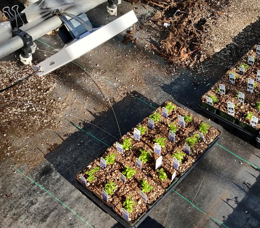
Potential Solutions:
- Figure out a new mounting situation for the RFID antenna that does not interfere with the irrigation boom water spray to bring it closer to the RFID tags.
- Through software, make the readings more sensitive for the antenna.
Redeployment is scheduled for Feb 25, 2020.
Author: Matt Guo
- Loom Libraries for SD and RTC have been added to the RFID Read
Show More
DescriptionThe RFID Module supports the OPEnS Hypnos Boards for SD logging and RTC functionality for the constant tag reading functionality. Using the SparkFun RFID Module Library and support, the RFID Reader can now fully display the RSSI, Moisture Value, Frequency of communication, and the customizable EPC of the tag. Below is a picture on the serial monitor showing these values.
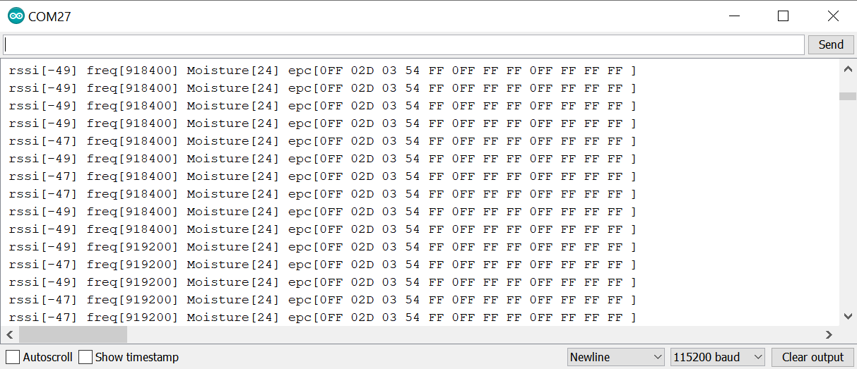
The RFID Moisture Feather functionality has now also expanded to writing customizable EPCs for individual tags, using the Feather_Write_EPC Feather M0 sketch. These customizable EPCs can be written directly on the sketch here:

With the Serial Monitor prompts showing as follows:

These combine for great flexibility on how the EPCs can be identified by the reader, and with the Loom module integration to the Constant Read sketch, can be used to log moisture data onto a local SD card, associating the moisture value to the specific, individual tags.

The data is saved onto a .csv file on the SD card, pulling and saving data from the RTC for time and date, EPC header, Moisture value, Frequency that was used for communication, and the RSSI of the signal. Below is a figure of the logged data.
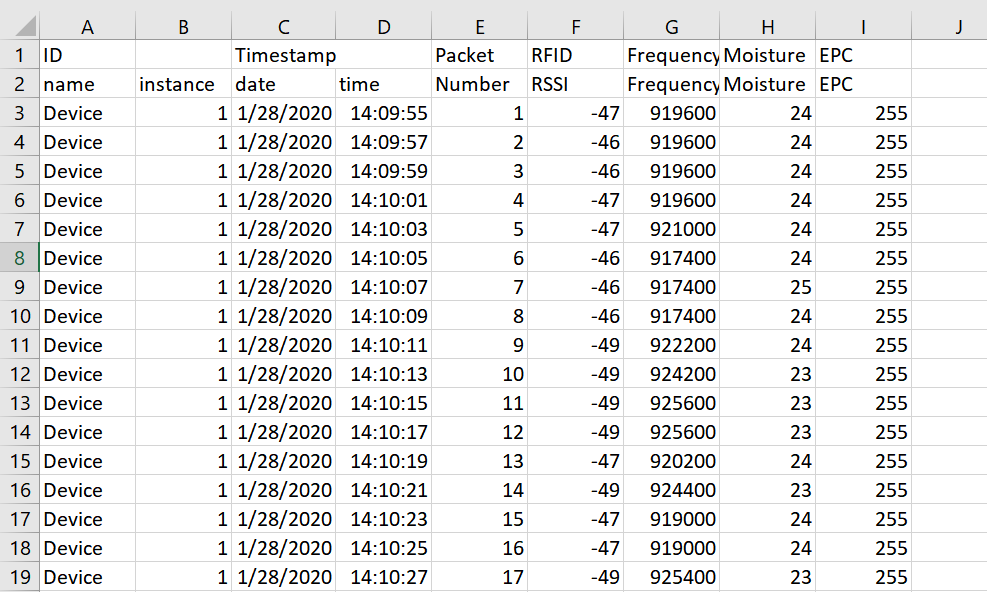
Future Revisions:
- Putting the entire EPC string and saving that into the .csv file instead of simply the header.
Author: Matt Guo
- Created a working unified PCB for the RFID Module and Feather M0
Show More
DescriptionA unified PCB that interfaces the RFID Module to the Feather M0 has been designed, soldered, and tested. This PCB contains necessary routing from the TX and RX lines (Pins 11 and 10 on the Feather M0) to the soft-serial port on the SparkFun Simultaneous RFID Reader (Pins 2 and 3 on the RFID Module). Two SN74AHCT125N Logic Level shifters are used on this board, one that level shifts from 3.3V to 5V for the RFID Module, and the other from 5V to 3.3V for the Feather M0. Below is a figure of the board file for the interface PCB.
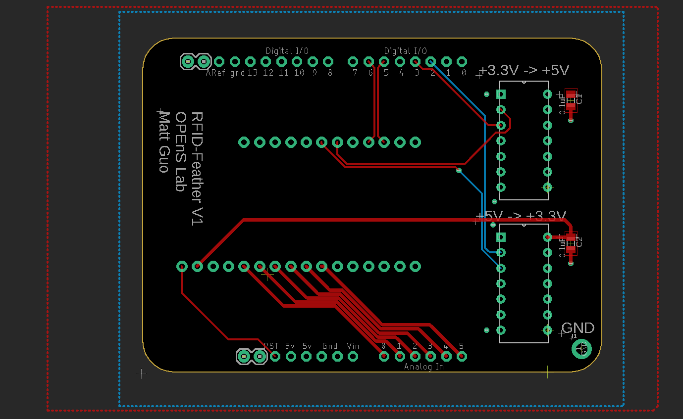
The top layer of the board lies the 5V plane from the USB pin of the Feather M0. This is what is used to power the 5V level shifter and the RFID Module. The bottom of the board contains the common ground plane. The "Analog In" ports of the RFID Module hookup, which is based off of the same topology as an Arduino UNO, is connected to GPIO A0 - A5 of the Feather M0, should additional GPIO be needed for this design.
The interface board sandwiches the Feather M0 and the RFID Module, with the RFID Module on the bottom and the Feather M0 on the top for ease of access. This is best illustrated in the pictures below.
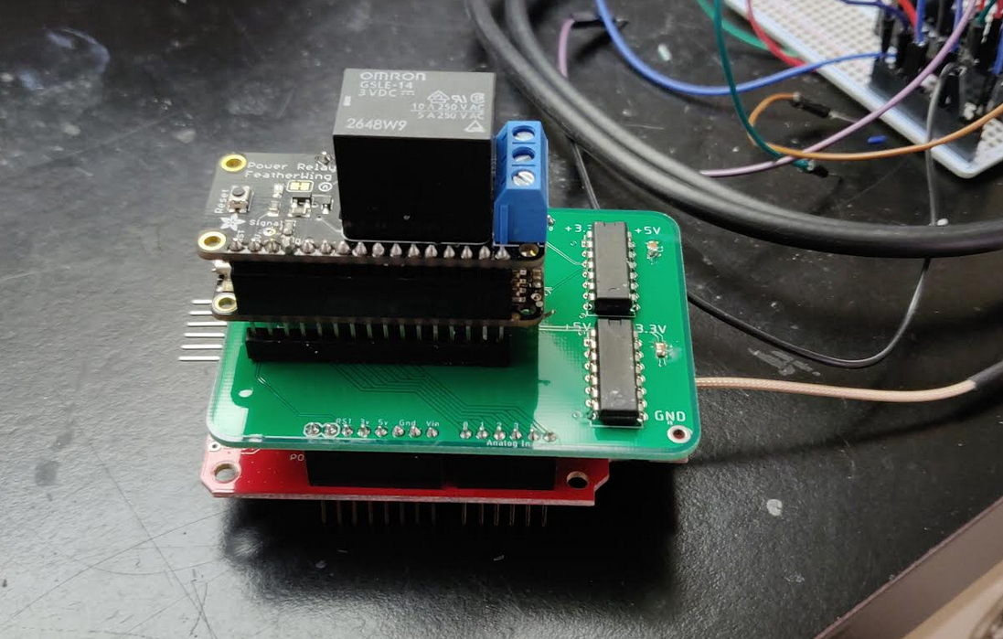
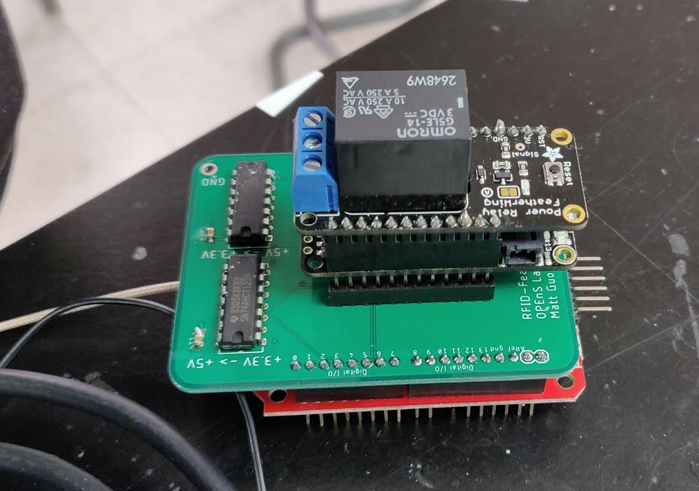
The red bottom board is the RFID Module, and two board on top of the interface board is the Feather M0 and the Adafruit Relay Switch used to control the irrigation system.
This board was also tested using the Arduino IDE and the revised Feather M0 skeleton code detailed in the previous update log. The 3.3V TX line from the Feather M0 is logic level shifted up to 5V for the RX line of the RFID Module, and the 5V TX of the RFID Module is then logic level shifted down to 3.3V for the Feather M0. The figure below illustrates proper initialization communication between the two.

Future Revisions
- A long header connection is mandatory between the Interface Board and the RFID Module. While not a future PCB revision, additional units to be soldered should take this into account.
- A silkscreen message for the Capacitor value size, which should be 0.1uF 0805, could be written on the top layer of the board for ease of soldering.
- Better Thermal relief connections of the GND pins of the SN74AHCT125N should be added for ease of soldering.
- Indicator LEDs from the 3.3V and 5V power rails of this board could be added to show proper interfacing of the Interface Board.
Resources
Author: Matt Guo & Max Chu
- Adafruit Soil Moisture Sensors deployed at Peoria Gardens
Show More
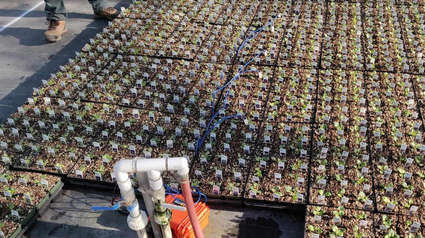
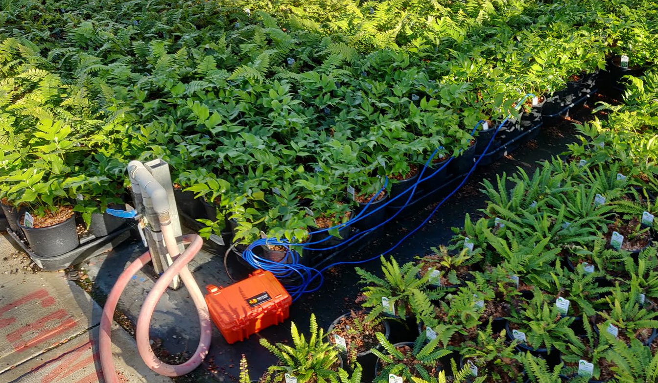
DescriptionThe Soil Moisture Dataloggers passed the OPEnS lab QA test, deeming it worthy to be deployed at Peoria Gardens. Three Dataloggers were deployed, with 5 Adafruit Capacitive Soil Moisture Sensors attached to each of the Dataloggers, bringing a total of 15 different sensors testing the moisture level of different soils. Each of the Dataloggers uses one Feather M0 with a multiplexer running on Loom and an OPEnS Hypnos Board to log the moisture value and the timestamp of the measurement. A 6 cell battery is used to power these Dataloggers, capable of a runtime of 10 days per single charge.
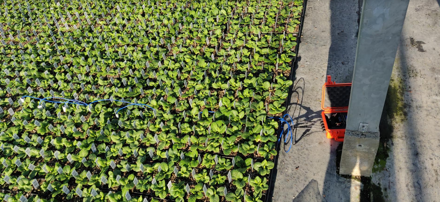
Below is the setup of a Datalogger:

The PORT number, start time, plant, and box numbers are listed below.
BOX 1 - Measuring Japanese Holly (start time: 2:14pm 11/21/2019)
- Furthest Sensor: PORT7
- 2nd Furthest Sensor: PORT5
- 3rd Furthest Sensor: PORT4
- 4th Furthest Sensor: PORT2
- Closest Sensor: PORT0
BOX2 - Measuring Pansy Fizzle Sizzle Mix (start time: 2:04pm 11/21/2019)
- Furthest Sensor: PORT0
- 2nd Furthest Sensor: PORT1
- 3rd Furthest Sensor: PORT4
- 4th Furthest Sensor: PORT6
- Closest Sensor: PORT7
BOX3 - Measuring Primula (start time: 2:24pm 11/21/2019)
- Furthest Sensor: PORT0
- 2nd Furthest Sensor: PORT1
- 3rd Furthest Sensor: PORT4
- 4th Furthest Sensor: PORT6
- Closest Sensor: PORT7
Author: Matt Guo
- Successful port of Sparkfun RFID constant read to Feather M0
Show More
Description
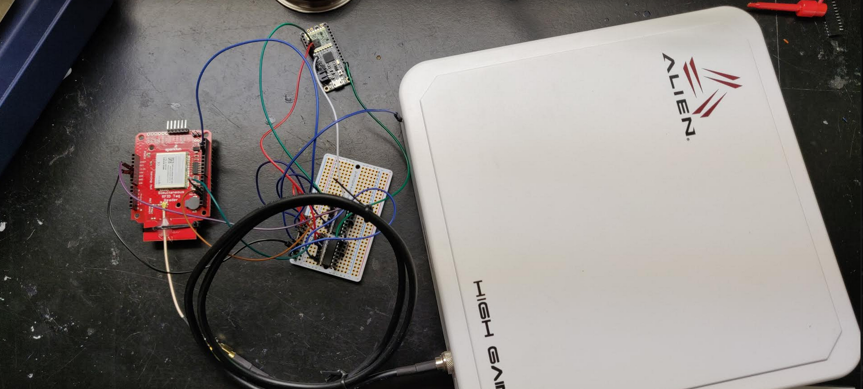
A successful port of the Sparkfun RFID constant read Arduino code to the Feather M0 has been made. To make this port successful, SN74AHCT125N logic level shifters were needed. These logic level shifters were used over the sparkfun breakout for their faster slew rates, required for high baud rate for the UART transmission. The SN74AHCT125N is a one-way logic level shifter - it can only go from 3.3V to 5V, or vice versa. The output logic level is dictated by the Vcc voltage. Two of these shifters were used for the design, one to transition from 3.3V to 5V, and the other going from 5V to 3.3V.
Below is the current setup for the RFID Soil Moisture Sensor Hardware:
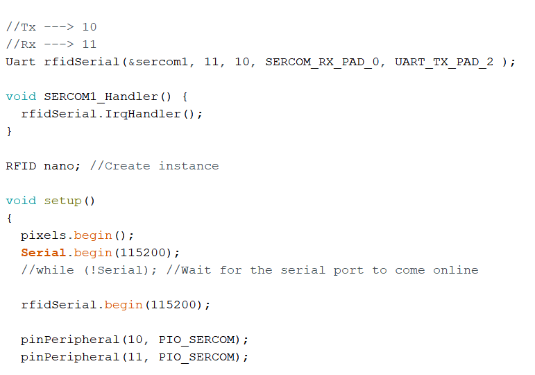
The original Sparkfun RFID constant read code for the Arduino Uno utilizes the softSerial library for Tx and Rx pins on GPIO 2 and 3. When porting over to the Feather M0, this softSerial library is not available, thus alternatives were needed. Adapted from Adafruit's website on 'Adapting Uno Sketches to the M0', PIO_SERCOM's pinPeripheral was initialized on the code to the Feather M0's pins 10 and 11 for Tx and Rx. This allows the creation of a new serial, arbitrarily called as rfidSerial, to be used whenever UART communication is needed in the sketch.
Error's occurred whenever the rfidSerial was closed and reinitialized to actively change the baud rate, which was initially handled in the setupNano() function from the Constant Read code. This was avoided by initializing the rfidSerial to a set baud rate of 115200 and leaving the communication handling to 115200.

References:
- Project Planning
- Prototyping
- Synthesis
- Lab Testing
- Field Testing
- Finalization/Production
- Poster/Presentation
- Publication
- CRES
- Dendrometer
- Djinn
- eDNA Sampler
- eGreenhouse
- Evaporometer
- FloDar
- HyperRail
- Hypnos
- Isotopic Sampler
- Lilypad
- Loom
- Micro-Aggregating Sewer Sampler
- Mooraca
- OPEnSampler
- Pied Piper
- Rag Guard
- Rain Gauge Calibrator
- RainSavor
- RFID Moisture
- Sap Flow Meter
- SitkaNet
- Slide Sentinel
- Smart Rock
- Spool
- WeatherChimes
- Weed Warden
- Wisp
- Archived Project Blogs