-
Notifications
You must be signed in to change notification settings - Fork 3
FloDar Updates
Author: Andrew Walker
- Accuracy vs. Flow Rate Experiment
Show More
To ensure the Ultrasonic Flowmeter selected for this system would provide accurate results, an experiment was devised to test the percent error in relation to the flow rate within the Calibration System mentioned below. The sensor's technical manual describes a limit to the accuracy associated with low flows, which was also seen in the experiment. However, the experiment also showed that as the flow rate increased the error rate decreased for most trials. Because mean error for the error rate increased between the final two flow settings, the experiment may need to be conducted again with higher flows to see if the error rate is parabolic or if the error rate truly shows a exponential approaching zero.
Testing Methodology:
- Turn on the pump at 20% of maximum flow rate
- Wait until all bubbles and air gaps have been removed from system
- If some gaps will not leave the system, turn the flow rate up to 40% until they leave and then turn back down to 20%
- Place your 500mL volumetric measuring equipment into the collection basin
- Turn on USFM
- Reset your stopwatch to zero
- With one hand, place outflow tube over your 500mL volumetric measuring equipment, starting the timer immediately
- Wait until 500mL has been reached then immediately stop the stopwatch
- Record trial
- Look at reading on USFM, record trial
- Turn off USFM
- Empty 500mL volumetric measuring equipment
- Repeat steps 3-11 until you have at least 5 trials for flow rate
- Repeat steps 3-12 for 30%, 40%, 50%, & 60%
Author: Andrew Walker
- New Lab Calibration System
Show More
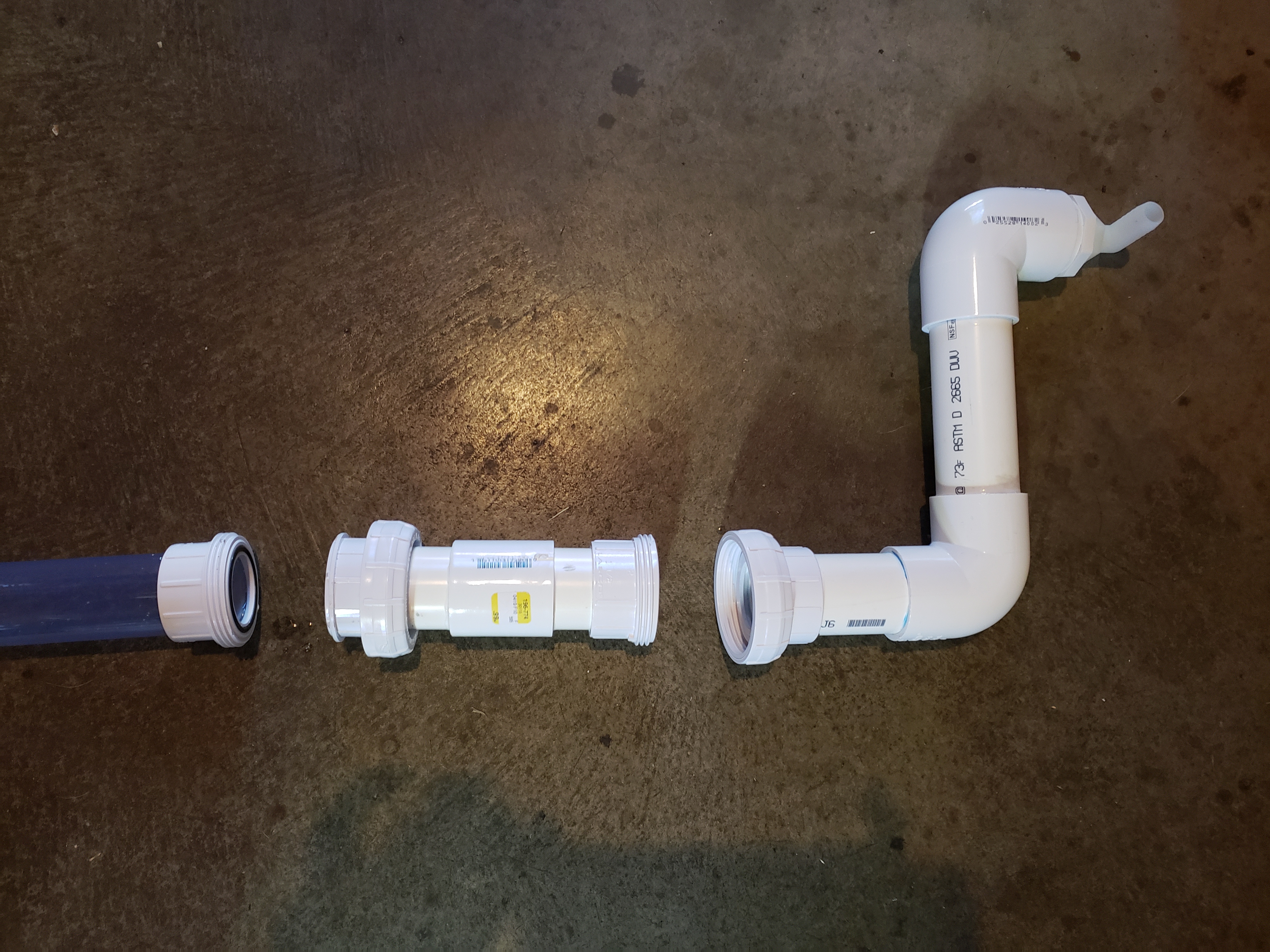
This section contains the removable & replaceable PVC housing for both the thermocouple and turbidity section. The unions at both ends allows for easy access to both components. The turbidity sensor is highly dependent on a clear pathway from one end to another for accurate reading. Because buildup can happen overtime, the user will be able to clear any debris if needed or a new section can be crated to take the place of a disfuctional piece.

This section connects the other end of the ultrasonic flowmeter section. This allows for easy calibration and creation for each new kit. With all preliminary testing complete, both sections can be removed and given to researchers to implement in the field. Both sides make it easy to insert in the field or reinsert in the lab system for any troubleshooting.

This is the whole lab system piping configuration. Both the left and right ends contain nozzles, the left acting as inlet and the right acting as outlet. These will stay in the lab and allow for efficient testing and calibration of the system.
Author: Andrew Walker
- Currently testing the sensors in the Lab
Show More
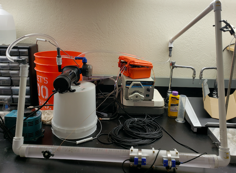
I have been testing the completed board and hardware configuration for a few weeks now. We are running into some issues with both the ultrasonic flowmeter and the turbidity sensor. We are hoping that creating a lab experiment that is more reflective of the current field use will increase the accuracy of the flowmeter, but for now the sensor is reporting values far too low. When the pump is on, bubbles and turbulence form in the fluid and may be the primary cause for inaccuracies. We will not know until we test, so we are hoping to make changes quickly.
The turbidity sensor has many problems associated with it at the moment. We are hoping to address these through collaboration between other OPEnS Lab members as it is in multiple projects. For now, the sensor can only indicate qualitative differences accurately, all quantitative measurements varying from one day to another. This will be an ongoing effort and we will do out best to update you as we make progress.
Author: Andrew Walker
- Schematic for the PCB made and sent in for validation.
Show More
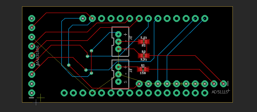
I think I have finally finished a completely integrated board for the FloDar project. It is currently being critiqued by the Chet and Cara, but it was a quite fulfilling project so far. We hope to know soon if it is good enough to get printed, populated, and implemented in the testing phase. Another large step toward finishing the first prototype of the project, but still many finishing touches to go!

Author: Andrew Walker
- Machined inserts for the thermocouple and turbidity sensor.
Show More
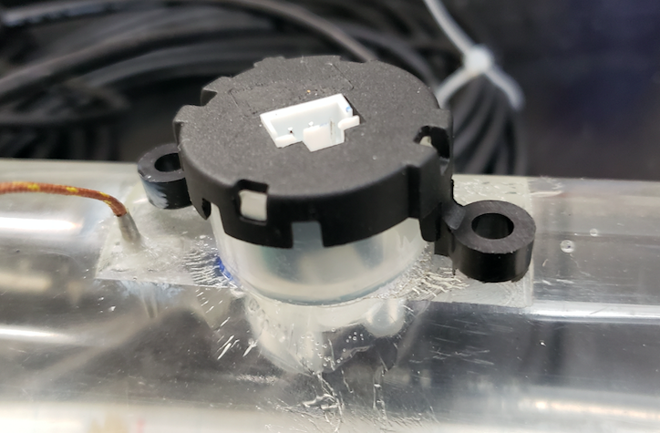
Hadi and Bradley worked in the OPEnS Machine Shop to created a new pipe with the turbidity and thermocouple sensors inserted and in contact with the water. Though it took two tries - the first pipe breaking due to the stress of the leveling process - the product turned out great and is ready to start testing! It has shown to be be water proof, now for accurate sensor measurements.
Author: Andrew Walker
- Created a functioning protoboard circuit for testing.
Show More
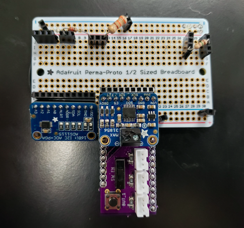
We have been working to make a protoboard of the circuit we will be using. The breadboard was a bit difficult to handle! Hopefully we will be able to convert this board to a proper PCB soon so that we can begin working towards a final prototype.
Author: Andrew Walker
- 3D printed a holder for the transducers to easy installation process.
Show More
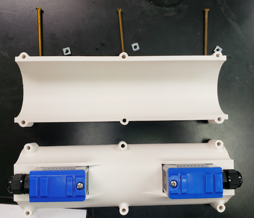
Hadi has created a great print to hold our flowmeter transducers. Installing the transducers has been a pain due to the awkward curve of the pipe and easy slippage. With the new compartments the transducers will be held in place while they are strapped down and set the exact distance apart thanks to the plastic spacing between them.
Author: Andrew Walker
- Created most of the bread board circuit necessary to power all components and transmit them to the ADS1115.
Show More
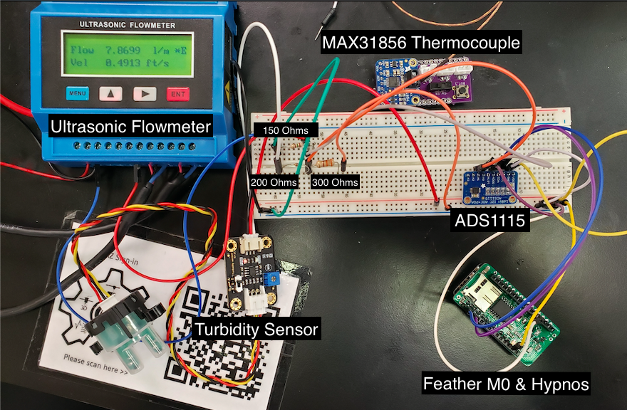
We are working on completing the necessary circuitry for the FloDar computing. So far we have implemented a 150Ohm resistor to convert the current analog from the flowmeter to voltage, implemented a voltage divider to step down the 5V from the turbidity sensor to 3V, and sending both signals to a 16 bit ADC for more accurate measurements.
- Project Planning
- Prototyping
- Synthesis
- Lab Testing
- Field Testing
- Finalization/Production
- Poster/Presentation
- Publication
- CRES
- Dendrometer
- Djinn
- eDNA Sampler
- eGreenhouse
- Evaporometer
- FloDar
- HyperRail
- Hypnos
- Isotopic Sampler
- Lilypad
- Loom
- Micro-Aggregating Sewer Sampler
- Mooraca
- OPEnSampler
- Pied Piper
- Rag Guard
- Rain Gauge Calibrator
- RainSavor
- RFID Moisture
- Sap Flow Meter
- SitkaNet
- Slide Sentinel
- Smart Rock
- Spool
- WeatherChimes
- Weed Warden
- Wisp
- Archived Project Blogs