-
Notifications
You must be signed in to change notification settings - Fork 1
ZapfBoard
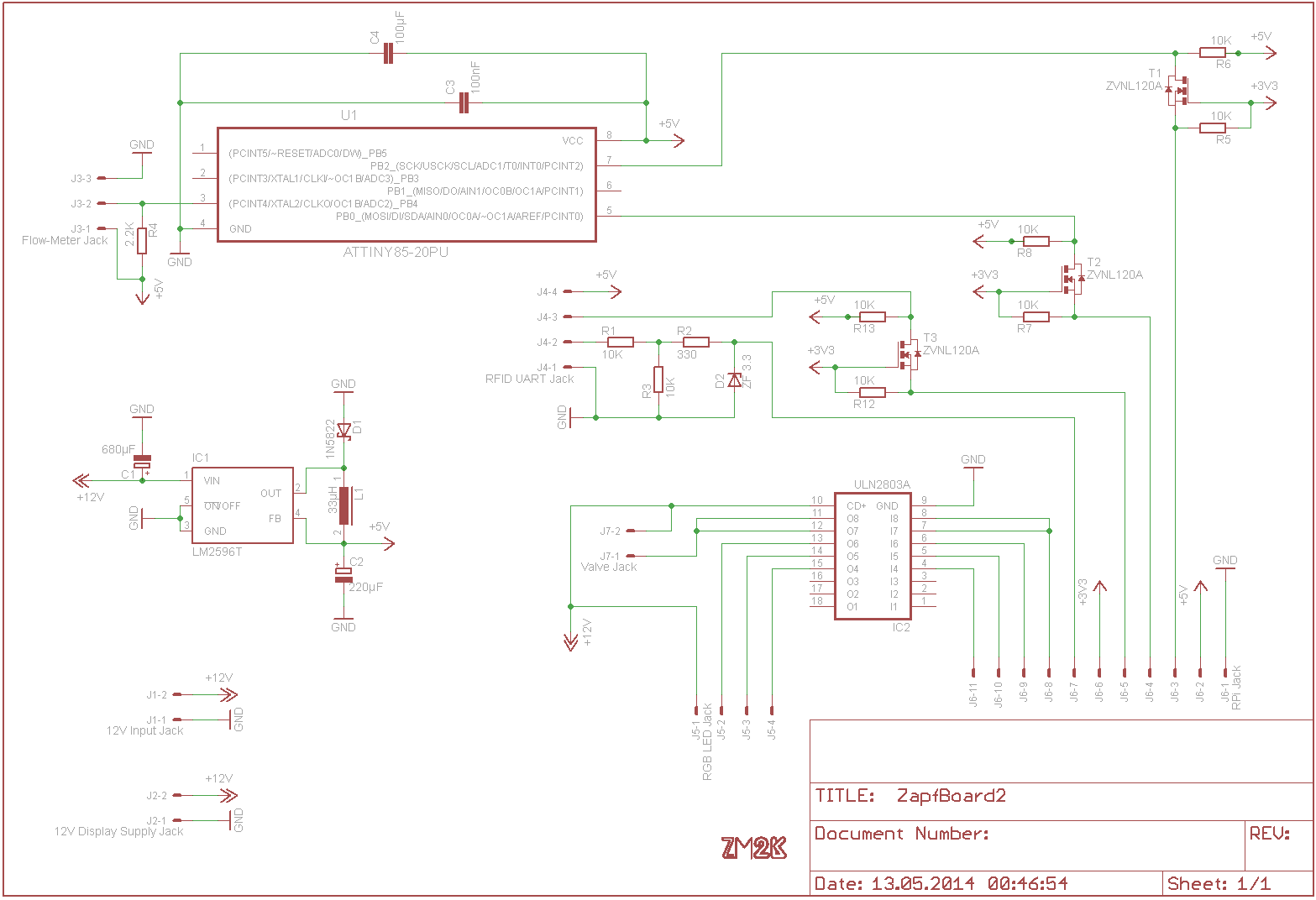
The ZapfBoard fulfills a multitude of purposes, mostly connecting peripherals to the Raspberry Pi. #ZapfBoard Functions ##Power distribution A 12V DC input jack provides power to the board and its 5V step-down driver. A second 12V Jack provides power to the display. Also the LED RGB strip and the valve are powered with 12V. ##5V power conversion The Raspberry Pi uses 5V supply voltage. A LM2596 step-down driver, which provides 5V is located on the ZapfBoard. Also the ATtiny85, the RFID-Reader and the SF800 flow meter use 5V supply voltage. ##ZapfCounter In order to determine the volume flowing through the ZapfLine the amount of ticks produced by the flow meter have to be counted. Since ticks per second determine the volume a correct read out during a specified time period is imperative. The Linux OS running on the Raspberry Pi is not a real time operating system and is therefore unequipped for this task.
An ATtiny85 microcontroller sums the ticks for every 500ms. It is attached to the Raspberry Pi using the I²C interface. The Raspberry Pi pulls the last sum from the ATtiny85. This component is called ZapfCounter. ##Logic level conversion The Raspberry Pis GPIOs operate on 3.3V. A 5V - 3.3V level conversion is present for the RFID-Readers UART port and the I²C interface. The 3.3V reference is provided through a pin on the Rapsberry Pi. ##Amplification A ULN2803A darlington driver is used in order to amplify the Raspberry Pi's output to 12V. This is done using one channel on the driver for each RGB channel of the LED strips and two driver channels for the solenoid valve. This is done because the valve uses 1A peak power and the ULN2803A only provides 0.5A per channel. It is recommended to install a passive cooler on the driver. #Electrical components ##Jack pinouts ###(J1) 12V Input Jack
| Pin Number | Pin Sign | Function |
|---|---|---|
| 1 | GND | Ground |
| 2 | +12V | +12V DC |
| ###(J2) 12V Display Supply Jack | ||
| Pin Number | Pin Sign | Function |
| :---------: | :--------: | :-------: |
| 1 | GND | Ground |
| 2 | +12V | +12V DC |
| ###(J3) Flow Meter Jack | ||
| Pin Number | Pin Sign | Function |
| :--------: | :------: | :------: |
| 1 | +5V | +5V DC Supply |
| 2 | Pulse | Flow Meter Frequency Pulse |
| 2 | GND | Ground |
| ###(J4) RFID UART Jack | ||
| Pin Number | Pin Sign | Function |
| :--------: | :------: | :------: |
| 1 | GND | Ground |
| 2 | TX | UART Tx Line, 9600 Baud, connects to RPi UART Rx |
| 3 | RX | UART Rx Line (currently unused, intended for NFC Device), connects to RPi, UART Tx |
| 4 | +5V | +5V DC Supply |
| ###(J5) RGB LED Jack | ||
| Pin Number | Pin Sign | Function |
| :--------: | :------: | :------: |
| 1 | G | Green PWM |
| 2 | B | Blue PWM |
| 3 | R | Red PWM |
| 4 | +12V | +12V DC Supply |
| ###(J6) RPi Jack | ||
| Pin Number | Pin Sign | Function |
| :--------: | :------: | :------: |
| 1 | GND | Ground |
| 2 | +5V | +5V Supply |
| 3 | I2C_SCL | I2C clock |
| 4 | I2C_SDA | I2C data |
| 5 | UART_RX | UART receive, RPi Tx (unused) |
| 6 | +3.3V provided by RPi | 01 |
| 7 | UART_TX | UART transmit, RPi Rx |
| 8 | VALVE | Valve PWM pin |
| 9 | LED_R | LED Strip Red PWM, PiBlaster Ch. 0 |
| 10 | LED_G | LED Strip Green PWM, PiBlaster Ch. 1 |
| 11 | LED_B | LED Strip Blue PWM, PiBlaster Ch. 4 |
| ###(J7) Valve Jack | ||
| Pin Number | Pin Sign | Function |
| :--------: | :------: | :------: |
| 1 | ctrl | ground which controls the state of the valve. open ground allows power flow and opens valve |
| 2 | +12V | 12V DC supply voltage |
##Bill of materials
A bill of materials for the current ZapfBoard can be found here
##Schematic
