Modifications
This is a cross-wiki maintained doc.
CX Cards are very cheep and flexible ADC chips as they can be modified for more sampling ability, signal filtering and connectors can be replaced and so on not only do they use standard parts but standard footprints for connectors and are also low cost enough to the point of not a high loss if mods fail badly.
CX White Card With C31 Removal Mod / BNC Mod / Crystal Mod

CX White Card With Cooling Mod / C31 Removal Mod / BNC Mod / External Clock Mod


- Software Defined Crystal Rate
- Improved Signal to Noise
- Hardware Synchronised Multi-Card Capture
- Hardware Synchronised Linear/Baseband Audio Capture
The most advanced mod available today, using an external crystal timing source we can have drift free capture with 2-4 CX Cards and audio feeds.
This allows duel channel video formats such as Betacam to be captured, or Video FM + HiFi FM + Linear for many other formats like VHS or Betamax.
Possible thanks to cxadc-clock-generator-audio-adc By Rene Wolf
External crystal timing via 2 additional PCB boards, a Jig with an SMA and Mainboard has allowed for under 50USD multi card sync, using 2 or more CX Cards alongside a extra input for synchronised Linear/Reference audio capture also has a extra input for headswiching timing signals.
-
Raspberry Pi Pico as the interface and control board.
-
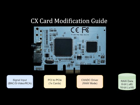
Adafruit Si5351A for generating the shared clock source with 5 potential inputs.
-
PCM1802 ADC for L/R input Linear/HiFi audio capture.


Audio Inputs and Head switch Input is on a dedicated bracket you can 3D print or modify a off shelf one.

USB Connection to Pi Pico provides control and audio feed.


The CX chips have an internal digital gain amplifier, which if used, can generate unwanted self noise. To mitigate this, you may use an external amplifier to increase the amplitude before it gets to the card, this can also compensate for longer cabling if unavoidable.
An amplifier is an affordable way to negate the issue and is a soft mod (via SMA cables soldered internally or soldered directly to bulkheads mounted on your VCR) to the capture chain in most setups for tape formats, and can even be powered by a VCRs internal 5V or 12V connections.
The ADA4857 board also provides a way to better match the impedance of the test point and put less load on it. The cx card by default is designed around capturing composite video signals with stronger signal levels which is not optimal and the extra load on the vcr amplifier caused by this can also potentially lead to some distortion on the output or other issues. (Analog video transmission is designed around 75 ohm impedance load).
| (Current) ADA4857 Dual Channel Amplifier | (Old) AD8367 AGC Amplifier |
|---|---|
 |
 |
The dual channel ADA4857 IC based amplifier board is has been designed to work well with the high impedance output from the VCR head amplifiers, ideal for CX Card based setups with stock 75ohm termination providing fixed gain amplification.
Tip
Do not use PCBway for less then 5 unit orders, you will pay 3 times more then KoFi for a single built amplifyer.
Order Links: ADA4857 KoFi & ADA4857 PCBway
Note
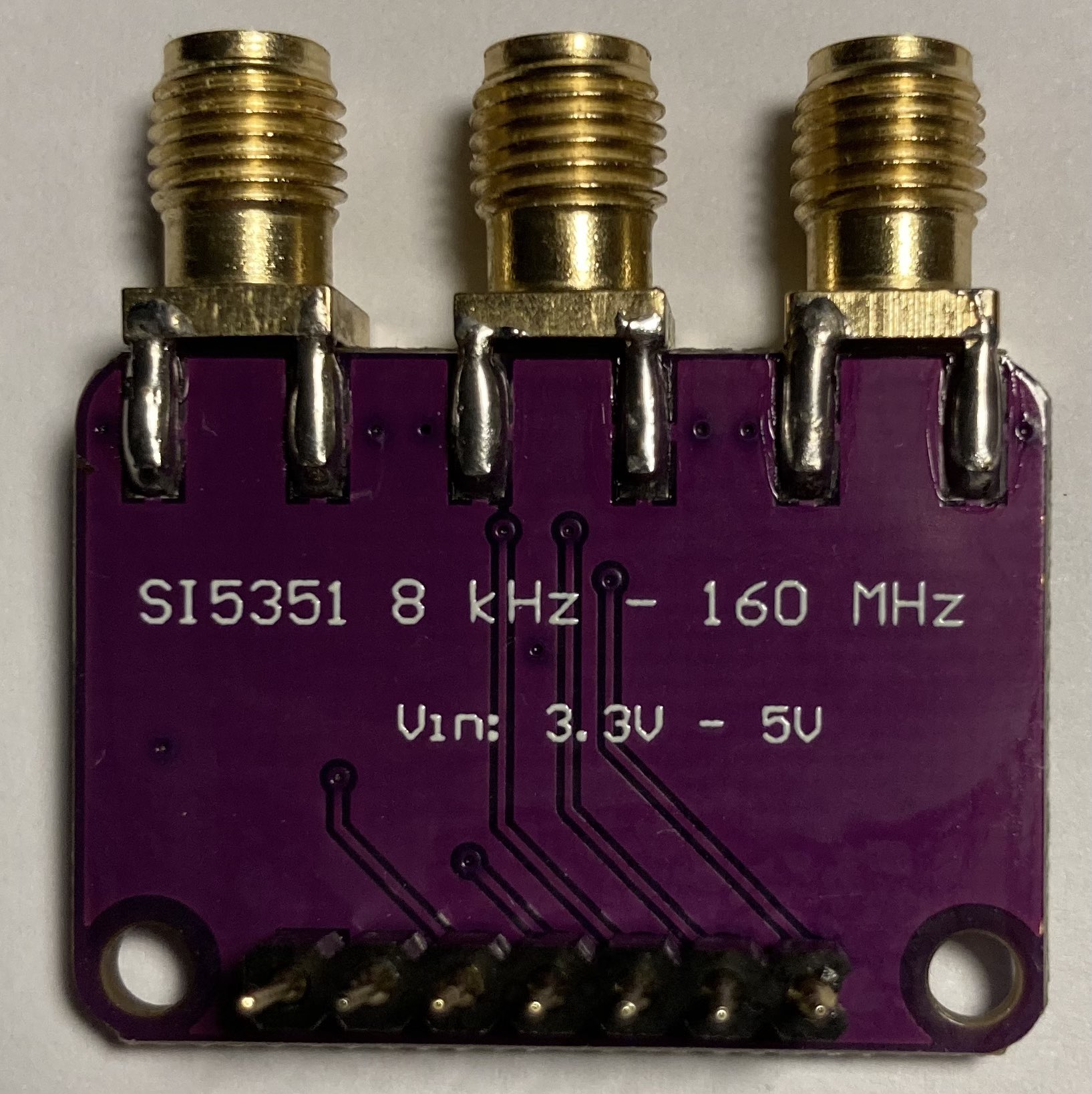
The AD8367 is no longer recommended as the input termination is internal to the IC, making it hard to modify to suit and match impedance for a VCR and the default 200ohm is often not optimal on all decks, if having issues please use the ADA4857 instead.
Caution
The AD8367 boards are 3-5v range only if voltage is 6-12v+ a buck boost converter or regulator to lower the voltage will be required. Jumper configuration in automatic gain mode "AGC" is both pairs with jumpers as shown in image.
AD8367 with Pot AliExpress Link / 4.5v AA Battery Holder
- Improved Signal to Noise

C31 is a capacitor that bridges the VUMX0 / VMUX1 inputs this causes more issues then anything else and so should be removed by soldering iron or plyers
- Faster Sampling Rate
- Improved Signal to Noise

This is the act of replacing the stock crystal with a faster rate crystal, note this crystal needs to be a fundamental type 3rd overtone will sometimes work but at lower rates.
At stock the CX Cards use a 28.63636 Mhz Crystal, this can be replaced with 40 Mhz fairly easily.
The max the CX chips support is 48Mhz to 54Mhz (according to the datasheet and testing) though this is rare to work outside the CX23881 version of the chip.
ABRACON ABLS2-40.000MHZ-D4YF-T Digikey / Farnell (can be sourced from most vendors)
Note
This mod helps improve stability and lifespan of any parts, the cooler something runs the better.

With higher sample rates or just long duration capture more cooling may be required to keep the CX chip at a stable temperature.
Installation:
-
Clean top of CX Chip with 99.9% IPA
-
Apply thermal pad or thermal paste.
-
Ensure conductive heatsinks does not contact with any electronic components it's best to capton tape the heatsinks and or surrounding components.


Blue cards come with BNCs but are not the most optimal cards, white cards come with RCA (both have S-Video or Y/C as well) as there is drop-in replacements available.
This requires de-soldering wicking & flush cutters,
The stock metal bracket will also need expanding by 1-2mm.
A Dremel with an small sanding bit or and a cutting wheel, or fine metal file is required for this.
Conformal coating is a layer of insulation this can provide light signal proofing and water/corrosion and debris protection.
By adjusting low pass filtering you can, get a softer or sharper look to images, this mainly applies to LD or LaserDiscs for capture however so tape users can mostly ignore this segment.