Servo Assembly hardware documentation #54
There are no files selected for viewing
This file contains bidirectional Unicode text that may be interpreted or compiled differently than what appears below. To review, open the file in an editor that reveals hidden Unicode characters.
Learn more about bidirectional Unicode characters
| Original file line number | Diff line number | Diff line change |
|---|---|---|
|
|
@@ -25,4 +25,6 @@ square-ish | |
| 70x84x20mm | ||
| 83x99x24mm | ||
| 4mm | ||
| 2.2A. | ||
| uno | ||
| 3.3V | ||
File renamed without changes.
File renamed without changes.
File renamed without changes.
This file contains bidirectional Unicode text that may be interpreted or compiled differently than what appears below. To review, open the file in an editor that reveals hidden Unicode characters.
Learn more about bidirectional Unicode characters
This file contains bidirectional Unicode text that may be interpreted or compiled differently than what appears below. To review, open the file in an editor that reveals hidden Unicode characters.
Learn more about bidirectional Unicode characters
This file contains bidirectional Unicode text that may be interpreted or compiled differently than what appears below. To review, open the file in an editor that reveals hidden Unicode characters.
Learn more about bidirectional Unicode characters
| Original file line number | Diff line number | Diff line change |
|---|---|---|
| @@ -0,0 +1,14 @@ | ||
| --- | ||
| title: GPIO | ||
| --- | ||
|
|
||
| The arduino allows you to connect your kit to your own electronics. It has 14 digital I/O pins, and 4 analogue. The analogue pins can read an analogue signal from 0 to 5V. The board also has a couple of ground pins, as well as some pins fixed at 3.3V and 5V output. | ||
|
|
||
| The pin layout of the servo assembly is the same as an Arduino uno. | ||
|
|
||
| 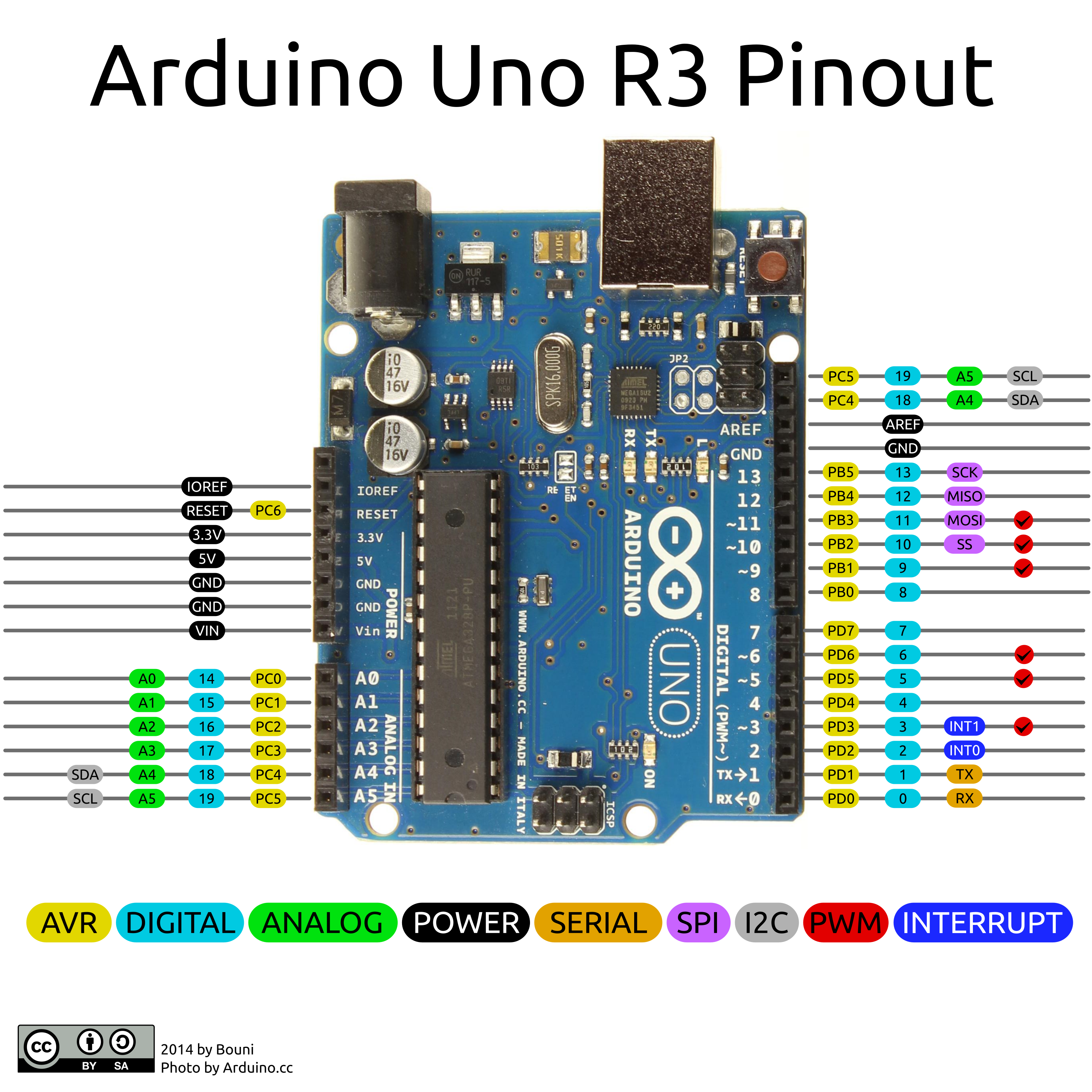 | ||
|
|
||
|
|
||
| {{% notice note %}} | ||
| The servo hat communicates using 2 of the analogue output pins (4 and 5), and so these are inaccessible. | ||
|
There was a problem hiding this comment. Please change "analogue output" -> "analogue input". Also, "inaccessible" -> "reserved". You can still physically plug stuff into them; it'll just make your servo shield behave weirdly. |
||
| {{% /notice %}} | ||
This file contains bidirectional Unicode text that may be interpreted or compiled differently than what appears below. To review, open the file in an editor that reveals hidden Unicode characters.
Learn more about bidirectional Unicode characters
| Original file line number | Diff line number | Diff line change |
|---|---|---|
| @@ -1,3 +1,21 @@ | ||
| --- | ||
| title: Servo Assembly | ||
| --- | ||
|
|
||
| The servo assembly allows you to control GPIO pins, Analogue pins, and servos. It's comprised of [an arduino](https://store.arduino.cc/arduino-uno-rev3), and a [servo hat](https://learn.adafruit.com/16-channel-pwm-servo-driver/overview). | ||
|
|
||
|  | ||
|
|
||
| ## The servo hat | ||
| The servo hat enables you to control up to 16 servos. It's attached to the top of the arduino, passing through its pins. | ||
|
|
||
| ## The reset button | ||
| The reset button allows you to instantly reboot the arduino in case it isn't working. This is not a guaranteed fix, however may solve the problem. | ||
|
|
||
|
|
||
| ## Designs | ||
| The board diagrams for both the Arduino and hat are below, as long as the custom firmware on the Arduino. You do not need this information to use the board but it may be of interest to some people. | ||
|
|
||
| - [Servo Hat Schematic](https://cdn-learn.adafruit.com/assets/assets/000/036/269/original/adafruit_products_schem.png) | ||
| - [Arduino Uno Schematic](https://www.arduino.cc/en/uploads/Main/Arduino_Uno_Rev3-schematic.pdf) | ||
| - [Firmware Source](https://github.com/sourcebots/servo-firmware) |
This file contains bidirectional Unicode text that may be interpreted or compiled differently than what appears below. To review, open the file in an editor that reveals hidden Unicode characters.
Learn more about bidirectional Unicode characters
| Original file line number | Diff line number | Diff line change |
|---|---|---|
| @@ -1,3 +1,11 @@ | ||
| --- | ||
| title: Servos | ||
| --- | ||
|
|
||
| By themselves, an Arduino is incapable of driving servos, without a lot of hard work and pin munging. So we're using a hat instead! This hat allows control of 16 servos. | ||
|
|
||
| ## Connecting your servos | ||
| There are a total of 16 servo connectors, grouped into 4 groups of 4. Servo cables are connected with 0V (the black or brown wire) towards the side of the reset button. | ||
|
|
||
| ## Power | ||
| The Arduino itself is powered entirely over USB. If you wish to use servos, you'll need to supply an additional 5V through the connector on the hat from the [power board](/kit/power-board). There are 2 red LEDs next to the power input, but these lights will turn on if the board is correctly powered. |
This file contains bidirectional Unicode text that may be interpreted or compiled differently than what appears below. To review, open the file in an editor that reveals hidden Unicode characters.
Learn more about bidirectional Unicode characters
| Original file line number | Diff line number | Diff line change |
|---|---|---|
| @@ -1,3 +1,16 @@ | ||
| --- | ||
| title: Ultrasound | ||
| --- | ||
|
|
||
| Ultrasound sensors are a useful way of measuring distance when objects are too close for the [Webcam](/api/webcam) to detect, or if they don't have markers. Ultrasound sensors communicate primarily over 2 pins. A signal is sent to the sensor on the _trigger_ pin, and the delay on a response on the _echo_ pin can be used to calculate the distance. | ||
|
|
||
| {{% notice warning %}} | ||
| Ultrasound should only be considered accurate up to around 2 metres, beyond that the signal can become distorted and produce erroneous results. | ||
| {{% /notice %}} | ||
|
|
||
| ## Wiring up the sensor | ||
| The sensor has 4 pin connections: ground, 5V, _trigger_ and _echo_. Most ultrasound sensors will label which pin is which. The ground and 5V should be wired to the ground and 5V pins of the arduino respectively. The trigger and echo pins should be attached to 2 different digital IO pins. Take note of these 2 pins, you'll need them to [use the sensor](/api/servo-assembly/ultrasound). | ||
|
|
||
| {{% notice tip %}} | ||
| If the sensor always returns a distance of 0, it means the _trigger_ and _echo_ pins are connected the wrong way! Either change the pins in the code, or swap the connectors. | ||
| {{% /notice %}} |
Loading
Sorry, something went wrong. Reload?
Sorry, we cannot display this file.
Sorry, this file is invalid so it cannot be displayed.
Add this suggestion to a batch that can be applied as a single commit.
This suggestion is invalid because no changes were made to the code.
Suggestions cannot be applied while the pull request is closed.
Suggestions cannot be applied while viewing a subset of changes.
Only one suggestion per line can be applied in a batch.
Add this suggestion to a batch that can be applied as a single commit.
Applying suggestions on deleted lines is not supported.
You must change the existing code in this line in order to create a valid suggestion.
Outdated suggestions cannot be applied.
This suggestion has been applied or marked resolved.
Suggestions cannot be applied from pending reviews.
Suggestions cannot be applied on multi-line comments.
Suggestions cannot be applied while the pull request is queued to merge.
Suggestion cannot be applied right now. Please check back later.
There was a problem hiding this comment.
Choose a reason for hiding this comment
The reason will be displayed to describe this comment to others. Learn more.
I'd recommend saying 6 analogue pins here rather than 4, since the you go on to say immediately below that two are reserved for the servo shield.