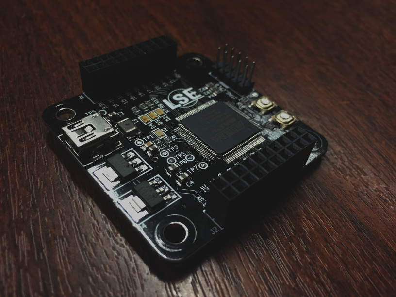
BMII is an open source general-purpose board controlled by USB and fully programmable with Migen.
It is based on an Altera Max V CPLD and a Cypress FX2LP.
from bmii import *

class PWMIOModule(IOModule):
    def __init__(self):
        IOModule.__init__(self, "PWM")

        self.cregs += CtrlReg("WIDTH", CtrlRegDir.RDWR)
        self.cregs += CtrlReg("COUNTER", CtrlRegDir.RDONLY)

        self.sync += self.cregs.COUNTER.eq(self.cregs.COUNTER + 1)

        self.iosignals += IOSignal("OUT", IOSignalDir.OUT)
        self.iosignals += IOSignal("NOUT", IOSignalDir.OUT)
        self.comb += self.iosignals.OUT.eq(self.cregs.COUNTER < self.cregs.WIDTH)
self.comb += self.iosignals.NOUT.eq(~self.iosignals.OUT)from bmii.ioctl.testbench import *
class PWMTestCase(IOModuleTestCase(PWMIOModule())):
def test_basic(self):
def gen():
yield self.tb.iomodule.cregs.WIDTH.eq(42)
yield
for i in range(41):
self.assertEqual((yield self.tb.iomodule.iosignals.OUT), 1)
yield
for i in range(214):
self.assertEqual((yield self.tb.iomodule.iosignals.OUT), 0)
yield
self.assertEqual((yield self.tb.iomodule.iosignals.OUT), 1)
self.run_with(gen())class PWM(BMIIModule):
def __init__(self):
BMIIModule.__init__(self, PWMIOModule(), PWMTestCase)
@classmethod
def default(cls, bmii):
pwm = cls()
bmii.add_module(pwm)
bmii.ioctl.sb.pins.LED0 += pwm.iomodule.iosignals.OUT
bmii.ioctl.sb.pins.LED1 += pwm.iomodule.iosignals.NOUT
bmii.ioctl.sb.pins.IO10 += pwm.iomodule.iosignals.OUT
return pwm
bmii_modules = [PWM]$ bmii -v -m pwm.py build all
[INFO] ixo.de USB JTAG firmware built
[INFO] USB controller firmware built
[INFO] IO controller design built$ bmii -v -m pwm.py program all
[INFO] [STAGE 1] Loading CPLD programmer firmware
[INFO] ixo.de USB JTAG firmware loaded
[INFO] [STAGE 2] Loading CPLD design
[INFO] Probe: USB-JTAG-BM [2-2]
[INFO] Model: 5M570Z/EPM570Z
[INFO] IDCODE: 020A60DD
[INFO] IO Controller configured
[INFO] [STAGE 3] Flashing EEPROM
[INFO] USB controller firmware flashed
[INFO] [STAGE 4] Loading USB firmware
[INFO] USB controller firmware loaded
[INFO] Found device (002:017)
[INFO] IDCODE: A5
[INFO] Device fully tested$ bmii -v -m pwm.py set PWM WIDTH 100
$ bmii -v -m pwm.py simulate PWM
[INFO] Simulating PWM
..
----------------------------------------------------------------------
Ran 2 tests in 0.156s

OK
For now, this board is handmade and therefore not yet distributed. However, If you are interested in getting your own BMII but are not brave enough to solder it yourself, just sent me a short email.
If enough people manifest their interests to order a board, a small batch will be manufactured. The estimated cost would be approximately 50 euros per unit.
