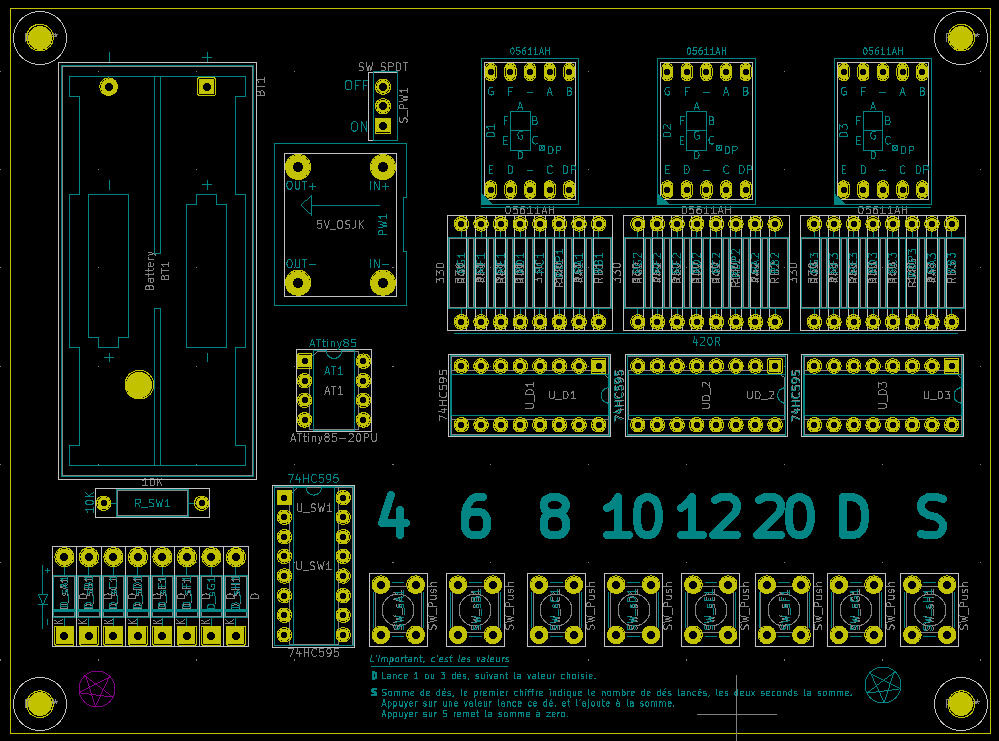
This project is an electronic dice that allow to launch 3D4, 3D6, 3D8, 3D10, 1D12, 1D20 or to compute the sum of launched dices. This project was designed to used common and cheap electronic components.
| quantity | reference | desciption | datasheet |
|---|---|---|---|
| 1 | 2468 | 2xAAA battery case | https://www.mouser.fr/datasheet/2/215/468-741064.pdf |
| 3 | 05611AH | 7 digit+decimal, common cathode, 0.56 inches | http://www.wayjun.com/Datasheet/Led/Segment%20Digit%20LED%20Display.pdf |
| 4 | 74HC595 | 8bits shift register,DIP16 | https://www.ti.com/lit/ds/symlink/sn74hc595.pdf |
| 4 | DIP16 support | ||
| 1 | ATTiny85 | DIP8 | https://ww1.microchip.com/downloads/en/DeviceDoc/Atmel-2586-AVR-8-bit-Microcontroller-ATtiny25-ATtiny45-ATtiny85_Datasheet.pdf |
| 1 | DIP8 support | ||
| 1 | 5V step up | (1) | |
| 24 | 330 ohms | Axial resistor, 1/4W (2) | |
| 1 | 10k ohms | Axial resistor, 1/4W (3) | |
| 8 | 1n4007 | Diode (4) | https://www.vishay.com/docs/88503/1n4001.pdf |
| 8 | 6x6mm push button | https://www.hdk.co.jp/pdf/eng/e291702.pdf | |
| 1 | ADD3 | RPG book, a good dungeon master, friends |
(1) This component is not referenced properly, I've found mine here https://www.aliexpress.com/item/32789971588.html but any pin compatible 5V step up will do the trick. The PCB was designed with extra space arount the 5V step up module, so you can easily edit it to use an other kind of module. The module looks like this.
(2) The 330 Ohms resistors are used to protect the 05611AH diodes. You must choose their value according to the kind of led you're using, and the desired brightness. The formula is R=(5-Vf)/If. Vf is the forward voltage of a single LCD segment, If is the segment forward intensity. Note that you must choose a value that's BIGGER than the one you've just computed.
(3) This resistor is used as a pulldown for switches, a wide range of values between 1K to 20K does the job.
(4) These diodes are used to protect the 74hc595 when we press more than one switch. The diode forward voltage drop must be lower than 2V in order to have sufficient voltage on the ATTiny85 input pin.