-
Notifications
You must be signed in to change notification settings - Fork 27
Wiring the drok
| Home | 1:Parts | 2:Hardware | 3:Software | 4:Data | 5:Wiring | About |
|---|
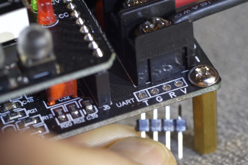
- Solder headers going down for the Drok's UART. They're on the right of the display and labeled T G R V.
- Important: The V-pin is 5V but has very little capacity. Don't use this to power your ESP32!! I destroyed a Drok and an esp32 trying that.😖
 |
|---|
| Pins closeup |
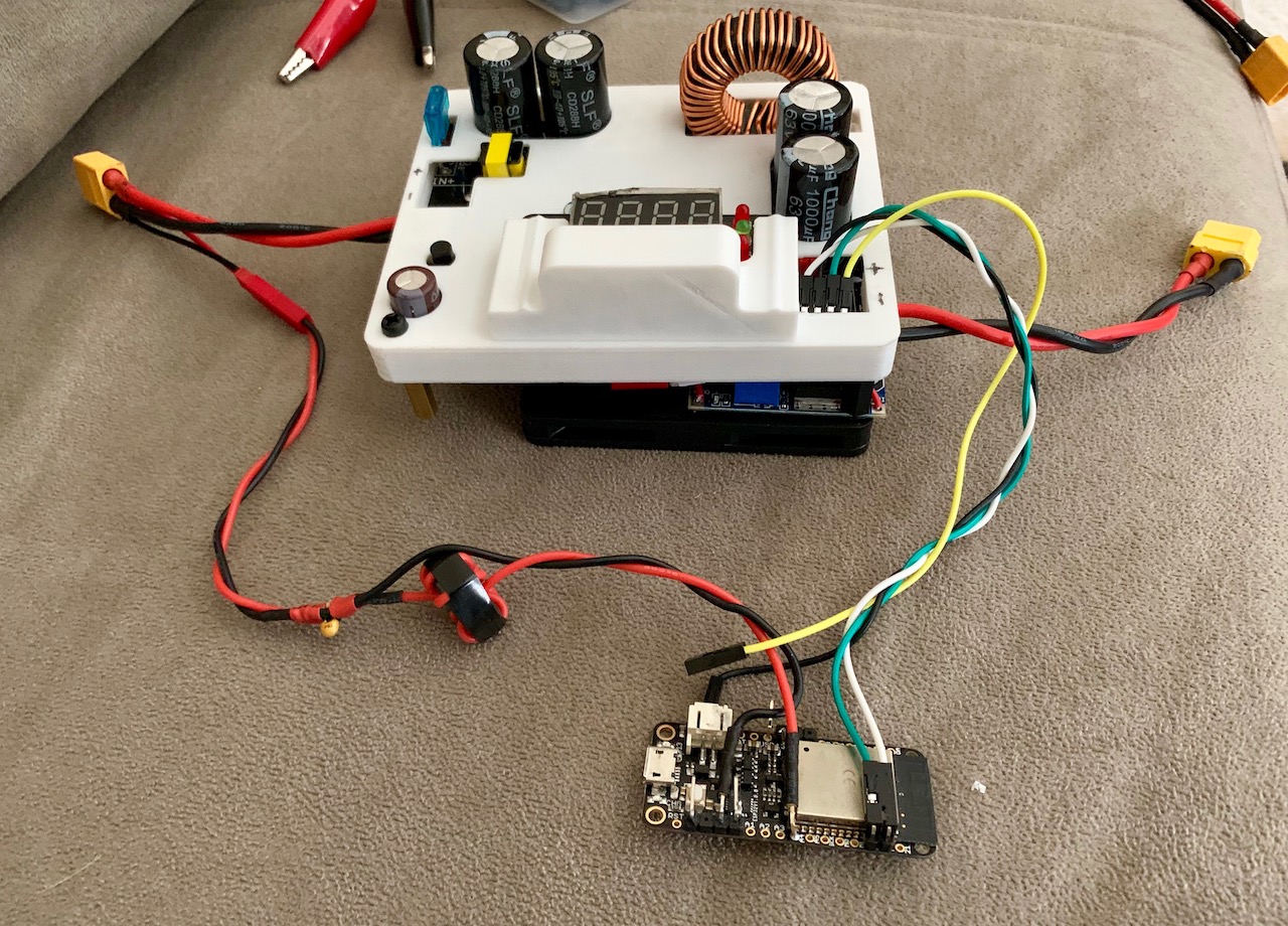
- Plug in a jumper between ESP32 pin GPIO-16(RX) to Drok T
- ESP32 GPIO-17(TX) to Drok R
- ESP32 GND to Drok G
Highly recommended: Use a paint pen (or silver sharpie) to color-code the ESP32 pins you use. This will reduce chance of plugging in to the wrong location and shorting things out and make connecting things easier every time.
- The ESP32 needs to read the solar panel / Drok input voltage.
- ESP32 GPIO-32 to solar +ve/-ve using voltage divider as follows:
- Use a 3.3kΩ and 100kΩ resistor to make a voltage divider to drop the input voltage down to within 3.3 for the ESP. Check your wiring with a volt meter before connecting it to your ESP.
 |
|---|
| an older example of a Drok and voltage divider wired up to XT60 connectors |
-
The DROK's fan only starts at either 3 or 5A... and it'll overheat and die after a short time with far less current.
-
You'll use the LM2596 (or LM2596-HV) regulator to power the included fan instead (or add in your own larger/quieter fan instead).
-
Wire the Drok's output screw-terminals to both your battery and your LM2596's input. Don't connect the output yet.
-
Wire a jumper between the Drok's hidden output-enabled pin and the LM2596 hidden ENABLE pin.
- This means your fan will only come on when the Drok output is enabled. Perfect.
-
On the LM2596: Desolder the furthest-right pin while gently bending it up with a small screwdriver or knife. Solder a wire from that to:
-
The Drok's pin on the bottom right next to the 'R032' jumper. See the photo.
PRO TIP: If a fan fails usually you'll just kill a MOSFET on your Drok. That's repairable. See the parts list optional section for a replacement and ask Tim about it on discord.
- First power-up the LM2596 and adjust the output voltage (using a screwdriver on the blue screw-potentiometer). I find they usually need to be turned counterclockwise ~4 times.
- Turn it down to 5V, connect your fan, then adjust to where you'd like.
- Connect to your fan with a wire. Regular 0.1" headers plug into fan connectors fine.
- The Drok PSU is awfully exposed... so I designed a case. Here's my thingiverse design which prints in ~1.5h without supports.
- development pending - Adjust Charging for Temperature Changes
- pin 13(GPIO12) / 1(3.3V) / 38(GND) to DS18B20 module.
Two potential issues:
- The ESP32's ADC is notoriously horifficly bad. Nonlinear noisy crap. See this article. The MPPT algorithm is resilient to this, it only needs to be accurate around the battery voltage.
- Use extra-thick gauge wires between the PSU and your battery. Too thin gauge wires on the output of a switching DC supply will create transient voltage spikes in everything– definitely including your serial wires to your ESP32.
The next step is to setup the wifi and setup mqtt database. Head there now!


