-
Notifications
You must be signed in to change notification settings - Fork 13
Live Playground
This page explains how to use the universal-node to create and deploy graphs through a live playgroung available @POLITO that allows to play with the universal-node without having to install all the modules.
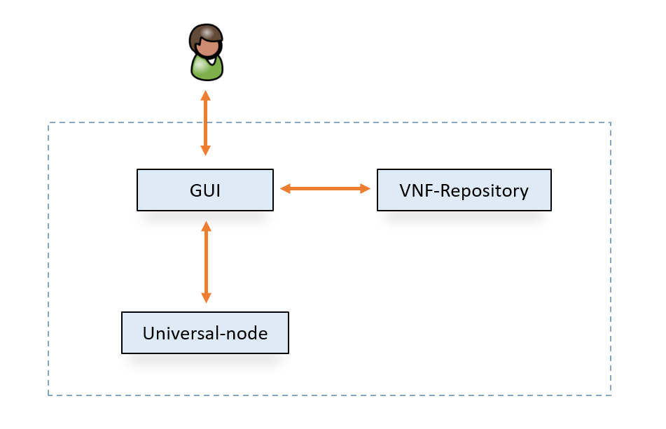
The main components of the scenario are the following.
Currently, the VNF-repository is in charge to provide the VNF templates to the GUI, so that the GUI knows which are the available VNFs. The GUI allows the creation of the graphs, with the VNFs provided from the VNF-repository, and the deployment on the universal-node, in addition to visualizing already instantiated graphs. The GUI is directly accessible at the URL http://130.192.225.236:9999/ using admin/qwerty as credentials.
Important warning: the live playground may have been used by some other users that forgot to delete their graphs. Therefore we strongly suggest to connect to the GUI first and list the graphs that are currently deployed (clicking on Open from Server) in the infrastructure. In case you find that the examples have already been deployed with the same graphIDs, either (a) delete the existing instances or (b) (better) deploy the graphs using new IDs in order to avoid conflicts.
As example we want to deploy a simple graph composed of two endpoints connected to each other through a simple VNF.
To draw a graph, a new document must be created by clicking on New Document.
An empty graph with random ID will be created. The user can change the graph id or assign a name and a description to the graph just touching the word ID on the right.
To start composing the graph, Draw menu button allows to create endpoints, VNFs and links.
In this example, first, we want to create two endpoints of type interface by clicking on End-Point button; first endpoint will be named eth1 and the second eth2, respectively if-name field in dialog box must contains the same values.
Note: The server which run the universal-node has only these interface:
eth1,eth2,eth3,eth4. Pay attention to use one of them in theif-namefield.
The Network Function Virtualization button shows a dialog box that allows users to create VNF by selecting a template from the available.
In this example we want to create a firewall, so select the firewall template and assign firewall as name of the VNF.
Note: Currently, to work properly, the VNF name must be the same of the VNF template name.
Port Info in dialog box allows to specify attributes of VNF ports and sometimes to create new VNF ports (according to the template).
In order to link endpoints to firewall VNF and firewall VNF to endpoints just click on Create Link, select the input element and then the output element; as a result create the flow rule.
Note: To create bidirectional link between A and B you must create 2 flow rules: A to B and B to A.
As a result, you should have a graph like the figure above. Now it is time to deploy the graph: Deploy button generates and sends the NF-FG json to the universal-node that completes the deployment of the graph. Once deployed, you can see the graph in the list of universal-node's deployed graphs.
Congratulations! Now you are able to use the GUI to create graphs using the provided VNFs!

