Skip to content
New issue

Have a question about this project? Sign up for a free GitHub account to open an issue and contact its maintainers and the community.

By clicking “Sign up for GitHub”, you agree to our terms of service and privacy statement. We’ll occasionally send you account related emails.

Already on GitHub? Sign in to your account

1/4, 1/8 scan panels #204

Open
mrcodetastic opened this issue Nov 9, 2021 · 84 comments
Open

1/4, 1/8 scan panels #204

mrcodetastic opened this issue Nov 9, 2021 · 84 comments

Comments

@mrcodetastic
Copy link
Owner

mrcodetastic commented Nov 9, 2021

image

Four-scan panels (aka. '1/8' on a 32px high LED matrix) use the same HUB75 connector and can be connected to the ESP32 in the same way as a 'half scan' (aka. '1/16' for a 32px high LED matrix, or '1/32' for a 64px high matrix), but additional software logic (pixel remapping) is required or the display will show garbage.

Four Scan Panel (aka. '1/8' on a 32px high LED matrix ) - Thank you to The Electronic Engineer for a 'four scan' (1/8) panel to get this to work.

For any other panel of a random scan type that doesn't work:

  • Somebody with these panel types needs to help code a solution; or
  • Sends us links to existing code (the specific code) that works with these panels (perhaps can easily copy paste) - lots of trial-and-error will be required from you to help find a solution; or
  • Simply send the contributors to this library a spare panel you might have so we can try code and test a solution ourselves.
@mrcodetastic mrcodetastic pinned this issue Nov 9, 2021
mrcodetastic added a commit that referenced this issue Nov 22, 2021
#154 #204

Also supports chaining.
@mrcodetastic mrcodetastic changed the title 1/2, 1/4, 1/8 scan panels 1/4, 1/8 scan panels Nov 23, 2021
@tsctrl
Copy link

tsctrl commented Dec 19, 2021

can this changes be integrated to the main branch? wondering how to re purpose existing virtual class than creating new instance for 1/8. the idea is to reuse existing virtual class but provide different initialization implementation that can be swap by configuration

@danieldecesaro
Copy link

danieldecesaro commented Jan 10, 2022

Dear @mrfaptastic,
In a issues #154. I reported the issue I was having with a 1/8 panel where the line was of only 16 LEDs and not 32 as you solved in the post in question.
Last week I thought about fixing this and fixed the problem with some small modifications to your library.
Are they:
enum PANEL_SCAN_RATE {NORMAL_ONE_SIXTEEN, ONE_EIGHT_32, ONE_EIGHT_16};
``
if ( _panelScanRate == ONE_EIGHT_16)
{
if ((y & 8) == 0) {
coords.x += (panelResX>>2) * (((coords.x & 0xFFF0)>>4)+1); // 1st, 3rd "block" of 8 rows of pixels, offset by panel width in DMA buffer
} else {
coords.x += (panelResX>>2) * (((coords.x & 0xFFF0)>>4)); // 2nd, 4th "block" of 8 rows of pixels, offset by panel width in DMA buffer
}

	if (y < 32)
		coords.y = (y >> 4) * 8 + (y & 0b00000111);
	else{
		coords.y = ((y-32) >> 4) * 8 + (y & 0b00000111);
		coords.x += 256;
	}
}

`
This apparently solved the problem and I managed to make a 4 panel dislay work perfectly, evidence follows;

  • 1/8 lines of 32 LEDs
    WhatsApp Image 2022-01-10 at 14 54 03 (1)

  • 1/8 lines of 16 LEDs
    WhatsApp Image 2022-01-10 at 14 54 03

@mrcodetastic
Copy link
Owner Author

Hi @danieldecesaro,
Fantastic work with that. Would you be able to raise a pull request or attach the modified virtual display class file if that's easier, and I'll incorporate.

@danieldecesaro
Copy link

Hi @mrfaptastic,

  Yes I can, I will do it soon!

Att.

@danieldecesaro
Copy link

Hi @mrfaptastic,
I just posted a proposed change, see if it's satisfactory. Thanks!

mrcodetastic added a commit that referenced this issue Jan 10, 2022
Implemented changes as proposed by @danieldecesaro in #204
@danieldecesaro
Copy link

Dear @mrfaptastic,
I'm doing more tests with different types of panels and I found a bug in the 1/16 scan panels.
In version 2.0.3 of the lib everything works perfectly, in version 2.0.6 or even in the master there are distortions in this type of panel. Evidence follows:
bug_1-16

I point out that I'm using a 2x2 setup but I see the same problem on individual panels as well. Using VirtualMatrixPanel, of course.

Can you guide me on what I should focus on to solve the problem?

Regards,

Daniel de Cesaro

@mrcodetastic
Copy link
Owner Author

mrcodetastic commented Jan 12, 2022

Have you tried changing the mxconfig.clkphase = false; config para to true or false and seeing that that makes a difference?

Some panels need an inverted (or not inverted) clock... causes stuff to be offset by a pixel on the x-coord.

Similar to the common issue raised in: #134

@danieldecesaro
Copy link

Hi @mrfaptastic,
Problem solved, thanks.
Att.

@board707
Copy link
Contributor

board707 commented Feb 17, 2022

Hi @mrfaptastic,
the problem with panels 1/4, 1/8 and similar is that for each type, for example 1/4, there are many variants for addressing rows and columns. Thus, it is impossible to write one code that will fit any matrix 1/4, there are dozens of variations. I work with such matrices, but for each one you have to choose it own version of the coordinate transformation

lefty01 pushed a commit to lefty01/ESP32-HUB75-MatrixPanel-I2S-DMA that referenced this issue Aug 1, 2022
@stsm1964
Copy link

stsm1964 commented Feb 1, 2023

Hi, I am new in this discussion.
Is there any new development on the 1/4 scan panel?
I am currently using "lefty01" 1/4 scan code to test my 32x16 1/4 scan LED module and run into issues.

@mrcodetastic
Copy link
Owner Author

Hi, I am new in this discussion. Is there any new development on the 1/4 scan panel? I am currently using "lefty01" 1/4 scan code to test my 32x16 1/4 scan LED module and run into issues.

As per @board707's comment, there are so many variants of the four-scan panels that it's probably a new type of panel you have.

Post photos and videos of running SimpleTestShapes example etc.

@oldcity83
Copy link

I have a p8 20*40 pixel rgb led matrix display panel. The driver uses an integrated ICN 2037, and has a scan rate of 1/5. Can you help me with this display. I'm thinking of running it with esp 32. none of the libraries worked. only 1 library worked but it is faulty..
https://github.com/2dom/PxMatrix#shiftreg_abc_bin_de

@DarrylStrong
Copy link

I have used that library and found it to work very well on 1/8 and 1/16 scan.

1.5 scan is an odd one and you will find very limited library support. But, how about setting up the library like a 1/8 scan; you will most likely just lose 3 out of the 8 scan lines but that can be mapped out.

@oldcity83
Copy link

I solved the problem of matrix panel with p8 20x40 pixels 1/5 scan rate. I managed to get it working with library https://github.com/2dom/PxMatrix#shiftreg_abc_bin_de. now i have problem with p10 rgb matrix panel which has 1/4 scan rate. there are only rows A and B. Again the same library ran, but one line works in reverse.

@board707
Copy link
Contributor

board707 commented Mar 1, 2023

i have problem with p10 rgb matrix panel

"p10" is say nothing about type of panel. What is the panel pixel dimensions - 32x16 pixels?

has 1/4 scan rate. there are only rows A and B

It seems that the panel has BINARY mux type.

one line works in reverse.

It is very strange. Lines on the led matrix ALWAYS paired. so your panel should has at least two reverse lines.
If you ready to test your panel with stm32 or RP2040 controllers, you can try my DMD_STM32 library

@tsctrl
Copy link

tsctrl commented Mar 17, 2023

hi @mrfaptastic ,

i run to an issue with p10 16X32px 4s RGB panel. i believe this panel is 1/4 panel by the 4s. the ic is 6124B which suppose supported by the library, and my thoughts say this panel each are 1/4 of size 32x64px panel. and assuming this panel will work by combining 4 panel to make up the resolution of 32x64px.
i am wrong, running the latest master branch with all the scan rate variation, and panel resolution changes by following the example does not work on my end, i am getting garbage display every time. this is common panels in market and i hope this panel will work.

20230318_073743-01

i will try to use the basic example and show the result later. at the mean time, do you have suggestion which configuration i could try to make this panel works?

Edit:
i have the test example ready with the result as below:
2_SimpleTestShapes.zip
1_SimpleTestShapes.ino only pin assignment was change with result as below:
IMG-20230318-WA0001

Four_Scan_Panel.zip
Four_Scan_Panel.ino only pin assignment was change with result as below:
https://user-images.githubusercontent.com/75555993/226074103-18bae0c6-750a-4e52-968e-5779c786853e.mp4

@mrcodetastic
Copy link
Owner Author

The only way to reverse engineer what is going on is to start with the basics. Draw a single pixel to reach led coordinate and then see what coordinate it actually shows up on. Use excel or something to log this.

Only then can one figure out how the panel works. Good thing though is all the LEDs are lit which hopefully means there isn't something else going on.

@mrcodetastic
Copy link
Owner Author

Also. If you perform a simple drawPixel(0,0) and get more than one pixel "lighting up" then there is some electrical/ signal issue.

@board707
Copy link
Contributor

4s panel can have binary or direct mux. if you confuse the mux type, then when one pixel is outputs in the code, several dots may lighting up on the matrix.
@tsctrl , I can help you to run your panel with my library, but with using STM32 or RP2040 as controller board

@tsctrl
Copy link

tsctrl commented Mar 18, 2023

hi @board707,

this is common panel available online. my intention to use this panel is due to p5 are too small for medium hall and i did not satisfies with the p5x3col setup that i use. it look tiny when it was in place. one good potential of having this panel support are we will be able to display larger display with minimum cost increase and open possibility to have more than 20 panels p10 as per resolution to be hookup(1p5 equal to 4p10 in resolution) to the tiny esp32. with the half resolution of p5, it is easier to configure the display by combining panels without having different screen design for p5 and p10.

sorry for the long write up, but i was really excited to have this panel to be supported. ok, so there is 3 common p10 panels with 32x16px configuration. this resolution and size, which is same as the original supported panel p5 with 32x64px. all p5 and p10 panels have the same width and height. 16cmx32cm. edit: by this condition. the panel are the same size and it is possible to have the casing/frame to be interchangeable or reuse between p5 and p10 panels. to add, p10 are the most common panels used for led display in the market as it is the cheapest and most cost effective for the usage.

3 common p10 panels (different by SMD led type, not to mention THT)

  1. code 2525 smd led. hub75. 1/8scan
  2. code 2727 smd led. hub75. 1/8scan
  3. code 3535 as the one i have. 1/4scan. the larges led size per pixel.

yup, thats mux thing i am not sure what this panel was and hoping this library to support it. i think, there are people who are able to use the 2727 led with 1/8 scan with this library. but to order/buy that panel will take some time to arrive, with unknown result but yet the best option is to have the 3535 1/4 scan to work with this library.

so iam hoping so much that this 3535 panel to be supported. iam not keen to design new board, pcb and new code from 0 for this. it will take years to complete.

@mrfaptastic, i will run some test to plot the pixel for this panel. i hope the binary or direct mux would not be the issue, seems someone also using binary libs to make this panel to work. also, you can sent me your address to [email protected] if you require some new panels for testing.

thanks

@board707
Copy link
Contributor

p5 and p10 panels have the same width and height. 16cmx32cm

The geometrical sizes of panels are not matter. The only important parameters are pixel resolution and scan pattern. 32x16 and 64x32 panels has completely different patterns and are not interchangeable.

iam not keen to design new board, pcb and new code

Ok, I understand. Good luck for your project

@tsctrl
Copy link

tsctrl commented Mar 18, 2023

hi @board707, thanks for the reply and your contributions. understand those scan patterns and resolution different. What does matter is what will it will display and is suppose to be the same for any different panels used with the same resolution regardless of panels quantity.

@board707
Copy link
Contributor

suppose to be the same for any different panels used with the same resolution regardless of panels quantity.

no, it wrong
From the library point of view 4 panels with 32x16 pixels are not the same as one 64x32

@mrcodetastic
Copy link
Owner Author

Please use the latest git master version of this library, the four scan example and the VirtualMatrixPanel class has been updated to fix a related issue.

@tsctrl
Copy link

tsctrl commented Mar 19, 2023

hi @mrfaptastic here is the test code and the result in excel:

chains and scan rates(CHAIN_TOP_RIGHT_DOWN/CHAIN_TOP_LEFT_DOWN) setting does not effecting this test result
FOURSCAN_PANEL_TEST.zip

4scan-test.xls

from the test the draw pixel only effecting half of the set x resolution, and added to 2 different rows
from the test the draw pixel only effecting 2 pixel of the set y resolution

this is the result of latest master 4_scan_panel.ino example (with custom pin assignment no other changes):
ino:
Four_Scan_Panel_2.zip
result:
https://user-images.githubusercontent.com/75555993/226169827-315ca2b3-1cf9-468f-9e54-a3050d6c6798.mp4
if i try to reduce the resolution to be 32x16 with FOUR_SCAN_16PX_HIGH i am getting blue green display but on half panel only.
let me know how can i test better or if this panel are actually not supported, i will try to get 1/8s FM5020 ic instead

thanks!

@board707
Copy link
Contributor

board707 commented Jul 19, 2023

Can you share fix for P8 20x40 Pixels 1/5 scan rate?

There can be many many variations of the scan patterns even for the same dimension matrices. Most likely that decision will not work for your matrix.
I think that the main problem is that we assume a linear pattern for multiscan matrices, but in most cases this is not the case.
A typical pattern is something like this:
1/4 patter image

@Thebluedragon7
Copy link

Can you share fix for P8 20x40 Pixels 1/5 scan rate?

There can be many many variations of the scan patterns even for the same dimension matrices. Most likely that decision will not work for your matrix. I think that the main problem is that we assume a linear pattern for multiscan matrices, but in most cases this is not the case. A typical pattern is something like this: 1/4 patter image

Can you share the one for P8? I have some questions regarding that; if you have some time maybe we can talk?

@board707
Copy link
Contributor

Can you share the one for P8?

No, I can't.
First, because the "P8" say nothing about matrix pattern, "8" is a simple inter-pixel distance in mm
And next because as I said, "there can be many many variations..." of it

I have some questions regarding that; if you have some time maybe we can talk?

Please asking the question here... or you prefer to use a private message?

@Thebluedragon7
Copy link

Thebluedragon7 commented Jul 19, 2023

It's P8-320x160 and has 1/5 scan. The resolution is 40x20.
Yes I'd much prefer private message @board707

@board707
Copy link
Contributor

board707 commented Jul 19, 2023

write me a message to

@metingul
Copy link

Hello,
is there any solution about P10 32X16 1/4 scan panels?

thank you @mrfaptastic ,

#include "ESP32-HUB75-MatrixPanel-I2S-DMA.h"
#include "ESP32-VirtualMatrixPanel-I2S-DMA.h" 

    // Panel configuration
  #define PANEL_RES_X 32 
  #define PANEL_RES_Y 16
  
  #define NUM_ROWS 1
  #define NUM_COLS 1 

  MatrixPanel_I2S_DMA *dma_display = nullptr;
  VirtualMatrixPanel  *FourScanPanel = nullptr;
  
  void setup()
  {
    ................
    HUB75_I2S_CFG mxconfig(PANEL_RES_X*2,  PANEL_RES_Y, NUM_ROWS*NUM_COLS,_pins );
    ................
    FourScanPanel = new VirtualMatrixPanel((*dma_display), NUM_ROWS, NUM_COLS, PANEL_RES_X, PANEL_RES_Y);
    FourScanPanel->setPhysicalPanelScanRate(EIGHT_SCAN_16PX_HIGH);
   }

  void loop() 
  {
      uint16_t color = FourScanPanel->color565(128, 0,0); //red
      for (int i = 0; i < PANEL_RES_X; i++)
      {
          for (int f = 0; f < PANEL_RES_Y; f++)
          {
            FourScanPanel->drawPixel(i,f, color);
            delay(50);
          }
      }
      delay(1000);
      FourScanPanel->clearScreen();
  } 

to work with 32x16px, i have to times 2 for the config so the x will expand to 64px and fill the panel to 32px on X axis:

mxconfig(PANEL_RES_X*2 ...

this is my silly codes i came out so far (this will move section 3 to 5, 4 to 6, 5 to 9 and so on) but i havent able to move 2 to 3, 4 to 7. since the Y is 16px so writePixel(0,12) will lit led at (0,0) for the second time. need to remap(0,12) to section 2 after section 2 to was remap to section 3. so writePixel(0,0) till writePixel(0, 16) will lit the led from top left to bottom.

    else if (panel_scan_rate == EIGHT_SCAN_16PX_HIGH)
    {
        if (virt_x > 7 && virt_x < 16){
			coords.x = virt_x+8;
		}else if (virt_x > 15 && virt_x < 24){
			coords.x = virt_x+16;
		}else if (virt_x > 23 && virt_x < 32){
                       coords.x = virt_x+24;
		}
    }

@board707
Copy link
Contributor

There are a lot of types 32x16 s4 panels with different scan patterns. You need to configure the mapping to each type separate, the mapping from one do not suits for another.

@quantum9903
Copy link

i have p6 32x32 display panel. Driver ICN2037 and scan 1/8 .using this library (ESP32-HUB75-MatrixPanel-DMA).i want to know what is mapping for 8 scan.
issue1
I'm getting error because of mapping issue.
@mrfaptastic

@board707
Copy link
Contributor

board707 commented Dec 5, 2023

Judging by the photo, your panel is simply filling up chaotically. No mapping will help here; first you need to get the panel to fill sequentially

@quantum9903
Copy link

here, value get from analog pin and generate spectrum chart(not chaotically)

@board707
Copy link
Contributor

board707 commented Dec 5, 2023

And what the point to show this picture here?
To figure out the mapping you should to run the test code that fill the matrix sequentally by columns and rows.

@quantum9903
Copy link

And what the point to show this picture here? To figure out the mapping you should to run the test code that fill the matrix sequentially by columns and rows.

code

img

still getting the error :(

@tsctrl
Copy link

tsctrl commented Dec 5, 2023

i have raised issue regarding this pattern, yes it is the new outdoor p10 with larger led and seems using common driver. but no one comeout with the mapping yet and i just hope someone will able to help

@board707
Copy link
Contributor

board707 commented Dec 5, 2023

but no one comeout with the mapping yet

Nobody will present you a mapping other than youself. To calculate the mapping someone should have the same panel in hands. Another way - record the video filling the matrix with pixel by pixel for at least a quarter of full panel and show the video in the issue - in that case you can hope somebody will develop the mapping from the video.

@tsctrl - by the way, I don't see your issue

@tsctrl
Copy link

tsctrl commented Dec 5, 2023

thank you @mrfaptastic ,

#include "ESP32-HUB75-MatrixPanel-I2S-DMA.h"
#include "ESP32-VirtualMatrixPanel-I2S-DMA.h" 

    // Panel configuration
  #define PANEL_RES_X 32 
  #define PANEL_RES_Y 16
  
  #define NUM_ROWS 1
  #define NUM_COLS 1 

  MatrixPanel_I2S_DMA *dma_display = nullptr;
  VirtualMatrixPanel  *FourScanPanel = nullptr;
  
  void setup()
  {
    ................
    HUB75_I2S_CFG mxconfig(PANEL_RES_X*2,  PANEL_RES_Y, NUM_ROWS*NUM_COLS,_pins );
    ................
    FourScanPanel = new VirtualMatrixPanel((*dma_display), NUM_ROWS, NUM_COLS, PANEL_RES_X, PANEL_RES_Y);
    FourScanPanel->setPhysicalPanelScanRate(EIGHT_SCAN_16PX_HIGH);
   }

  void loop() 
  {
      uint16_t color = FourScanPanel->color565(128, 0,0); //red
      for (int i = 0; i < PANEL_RES_X; i++)
      {
          for (int f = 0; f < PANEL_RES_Y; f++)
          {
            FourScanPanel->drawPixel(i,f, color);
            delay(50);
          }
      }
      delay(1000);
      FourScanPanel->clearScreen();
  } 

to work with 32x16px, i have to times 2 for the config so the x will expand to 64px and fill the panel to 32px on X axis:

mxconfig(PANEL_RES_X*2 ...

this is my silly codes i came out so far (this will move section 3 to 5, 4 to 6, 5 to 9 and so on) but i havent able to move 2 to 3, 4 to 7. since the Y is 16px so writePixel(0,12) will lit led at (0,0) for the second time. need to remap(0,12) to section 2 after section 2 to was remap to section 3. so writePixel(0,0) till writePixel(0, 16) will lit the led from top left to bottom.

    else if (panel_scan_rate == EIGHT_SCAN_16PX_HIGH)
    {
        if (virt_x > 7 && virt_x < 16){
			coords.x = virt_x+8;
		}else if (virt_x > 15 && virt_x < 24){
			coords.x = virt_x+16;
		}else if (virt_x > 23 && virt_x < 32){
                       coords.x = virt_x+24;
		}
    }

image

this one @board707 , it is 8 months old. with lots of your helping comments. seem others waiting for the same solution for this panel too.

i wish i could do it my self like you do.. but seems you didnt care about to support people here with solution rather than implementing the fix on your own library for diffrent mcu. are u being sponsored?what a shame. 😄

@board707
Copy link
Contributor

board707 commented Dec 5, 2023

I know the structure of matrices, but I don’t know this library code very well. Therefore, I help with general advice and do not give ready-made solutions. Hope your understanding :)

@KuDesNikdid
Copy link

It's P8-320x160 and has 1/5 scan. The resolution is 40x20. Yes I'd much prefer private message @board707

please help... Need fix for that matrix.

@board707
Copy link
Contributor

board707 commented Feb 4, 2024

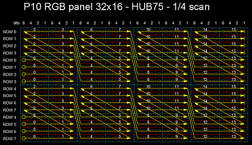
I believe that co-ordinate transformations for 1/4 1/8 panels in VirtualMatrixPanel class could be simplificated.

The FourScan panel from the starting picture:
FourScan2
is a special case of a more general set of panels, where two rows are updated in parallel.
These rows can be filled sequentially on the entire width of the matrix - or maybe in parts. In general, filling out the panel looks like this:
dmd_64_32a
I called the number of pixels that are filled in the same row at once - the Pixelbase.
For the panel in first picture, Pixelbase is equal to the width of the panel.
In the VirtualMatrixPanel class there are transformations for such panels - one for panels with a pixel base of 16, the other for 32.
In fact, all such panels are described in one form:

inline VirtualCoords OneEightScanPanel::getCoords(int16_t &x, int16_t &y) {
  VirtualMatrixPanel::getCoords(x, y); // call to base to update coords for chaining approach
  
uint8_t PanelHalfHeight = panelResY >> 1;
uint8_t PanelQuarterHeight = panelResY >> 2;

  if ( coords.x == -1 || coords.y == -1 ) { // Co-ordinates go from 0 to X-1 remember! width() and height() are out of range!
    return coords;
  }

  if ( (y & PanelQuarterHeight ) == 0) { 
    coords.x += ((coords.x / Pixelbase)+1)* Pixelbase; // 1st, 3rd 'block' of 8 rows of pixels, offset by panel width in DMA buffer
  }
  else {
    coords.x += (coords.x /  Pixelbase)* Pixelbase; // 2nd, 4th 'block' of 8 rows of pixels, offset by panel width in DMA buffer
  }

 
  coords.y = (y >>PanelHalfHeight )* PanelQuarterHeight + (y & ( PanelQuarterHeight -1));   
 
  return coords;
}

@saka2080
Copy link

saka2080 commented Mar 21, 2024

I solved the problem of matrix panel with p8 20x40 pixels 1/5 scan rate. I managed to get it working with library https://github.com/2dom/PxMatrix#shiftreg_abc_bin_de. now i have problem with p10 rgb matrix panel which has 1/4 scan rate. there are only rows A and B. Again the same library ran, but one line works in reverse.

@oldcity83
I have same problem with P8 20*40 1/5, can you help me to solve this problem.

@RoganDawes
Copy link

I have two "8 scan panel" (https://www.aliexpress.us/item/1005003238025086.html), and a Huidu WF1 controller (also have a WF2 if necessary).
I have been able to get it working using the following code:

#ifdef IDF_BUILD
#include <stdio.h>
#include <freertos/FreeRTOS.h>
#include <freertos/task.h>
#include <driver/gpio.h>
#include "sdkconfig.h"
#endif

#include <Arduino.h>
#include "xtensa/core-macros.h"
#include "main.h"

#include "ESP32-HUB75-MatrixPanel-I2S-DMA.h"
#include "ESP32-VirtualMatrixPanel-I2S-DMA.h" 

/*  Default library pin configuration for the reference
  you can redefine only ones you need later on object creation */
#define R1 2
#define R2 4
#define G1 6
#define G2 8
#define BL1 3
#define BL2 5
#define CH_A 39
#define CH_B 38
#define CH_C 37
#define CH_D 36
#define CH_E 12
#define OE 35
#define CLK 34
#define LAT 33

  // Panel configuration
  #define PANEL_RES_X 64 // Number of pixels wide of each INDIVIDUAL panel module. 
  #define PANEL_RES_Y 32 // Number of pixels tall of each INDIVIDUAL panel module.
  
  #define NUM_ROWS 1 // Number of rows of chained INDIVIDUAL PANELS
  #define NUM_COLS 2 // Number of INDIVIDUAL PANELS per ROW
  
  MatrixPanel_I2S_DMA *dma_display = nullptr;
  VirtualMatrixPanel  *FourScanPanel = nullptr;
  
  void setup()
  {
    Serial.begin(115200);
    HUB75_I2S_CFG::i2s_pins _pins={R1, G1, BL1, R2, G2, BL2, CH_A, CH_B, CH_C, CH_D, CH_E, LAT, OE, CLK};

    HUB75_I2S_CFG mxconfig(
                PANEL_RES_X*2,              // DO NOT CHANGE THIS
                PANEL_RES_Y/2,              // DO NOT CHANGE THIS
                NUM_ROWS*NUM_COLS,          // DO NOT CHANGE THIS
                _pins
    );
    
    mxconfig.clkphase = false;
    mxconfig.driver   = HUB75_I2S_CFG::FM6124;
    dma_display = new MatrixPanel_I2S_DMA(mxconfig);
    dma_display->setBrightness8(64);
  
    if (not dma_display->begin())
      Serial.println("****** !KABOOM! I2S memory allocation failed ***********");
   
    dma_display->clearScreen();
    
    FourScanPanel = new VirtualMatrixPanel((*dma_display), NUM_ROWS, NUM_COLS, PANEL_RES_X, PANEL_RES_Y);
    FourScanPanel->setPhysicalPanelScanRate(FOUR_SCAN_32PX_HIGH);
  }

  // draws blocks of 16x8 pixels from left to right, top to bottom
  // demonstrates the coordinate remapping required to make them
  // appear where expected
  void blocks() {
    auto c = dma_display->color565(128, 0, 0);
    for (uint8_t y=0; y<32; y+=8) {
      // make stripes of red, green, blue, white
      if (y < 8)
        c = dma_display->color565(128, 0, 0);
      else if (y < 16)
        c = dma_display->color565(0, 128, 0);
      else if (y < 24)
        c = dma_display->color565(0, 0, 128);
      else if (y < 32)
        c = dma_display->color565(128, 128, 128);

      for (uint8_t x=0; x<128; x++) {
        // pause briefly after each block of 16*8 pixels
        // if ((x % 16) == 0) delay(250);

        for (uint8_t z=0;z<8;z++) {
          uint8_t v=x;
          uint8_t w=y+z;
          if (w&8) {
            if ((v&63)<16) {
            } else if ((v&63)<32) {
              v^=48;
            } else if ((v&63)<48) {
              v^=32;
              w^=8;
            } else if ((v&63)<64) {
              v^=16;
              w^=8;
            }
          } else {
            if ((v&63)<16) {
              v^=16;
              w^=8;
            } else if ((v&63)<32) {
              v^=32;
              w^=8;
            } else if ((v&63)<48) {
              v^=48;
            } else if ((v&63)<64) {
            }
          }
          FourScanPanel->drawPixel(v,w,c);
        }
      }
    }
  }

  void loop() {
      blocks();
      delay(2000);
      dma_display->clearScreen();
  }

This works for the two panels daisy chained together.

What is the "correct" way to implement the mapping, so that "user code" such as drawing circles, text, etc, "just works"(tm) ?

@RoganDawes
Copy link

More digging surfaced the getCoords() function. I presume the idea is to extend VirtualMatrixPanel and override it.

This seems to work so far:

class MyVMP : public VirtualMatrixPanel {
public:
    MyVMP(MatrixPanel_I2S_DMA &disp, int _vmodule_rows, int _vmodule_cols, int _panelResX, int _panelResY, PANEL_CHAIN_TYPE _panel_chain_type = CHAIN_NONE) : VirtualMatrixPanel(disp, _vmodule_rows, _vmodule_cols, _panelResX, _panelResY, _panel_chain_type) {}

    virtual VirtualCoords getCoords(int16_t x, int16_t y);

};

inline VirtualCoords MyVMP::getCoords(int16_t virt_x, int16_t virt_y)
{
  if (virt_y&8) {
    if ((virt_x&63)<16) {
    } else if ((virt_x&63)<32) {
      virt_x^=48;
    } else if ((virt_x&63)<48) {
      virt_x^=32;
      virt_y^=8;
    } else if ((virt_x&63)<64) {
      virt_x^=16;
      virt_y^=8;
    }
  } else {
    if ((virt_x&63)<16) {
      virt_x^=16;
      virt_y^=8;
    } else if ((virt_x&63)<32) {
      virt_x^=32;
      virt_y^=8;
    } else if ((virt_x&63)<48) {
      virt_x^=48;
    } else if ((virt_x&63)<64) {
    }
  }
  VirtualMatrixPanel::getCoords(virt_x, virt_y);
  return coords;
}

then setup() has:

vmp = new MyVMP((*dma_display), NUM_ROWS, NUM_COLS, PANEL_RES_X, PANEL_RES_Y);

Now all drawing methods operate on "natural coordinates", without having to recalculate anything, and methods such as vmp->print(str[w]); work as expected.

Thanks for the excellent library.

@board707
Copy link
Contributor

board707 commented Oct 9, 2024

Hi @RoganDawes
Your getcoords code looks overcomplicated. I am sure I can do it shorter and simpler if you let me run a few tests on your matrix.

@RoganDawes
Copy link

RoganDawes commented Oct 9, 2024

Sure, happy to try some variations. I certainly did consider alternatives with unconditional shifting, etc, but that also seemed rather complicated.

This is the layout of the blocks (16*8 dimensions)

  6  8  2  4
  5  7  1  3
 14 16 10 12
 13 15  9 11

i.e. if I draw a pixel at (0,0), it shows up in the top left corner of block 1, if I draw a pixel at (16,0), it shows up in block 2, (0,8) shows up in block 5, etc.

Observation is that the sequence in the top two rows of the diagram above is repeated in the lower two rows, and blocks 4, 5, 12, 13 are already in the right place.

Perhaps some comments will help:

inline VirtualCoords MyVMP::getCoords(int16_t virt_x, int16_t virt_y)
{
  if (virt_y&8) { // handle rows 2 and 4, i.e. y in (8,15) or (24,31) (or higher)
    if ((virt_x&63)<16) { // handle block 5 and 13 (do nothing)
    } else if ((virt_x&63)<32) { // handle block 6 and 14
      virt_x^=48;
    } else if ((virt_x&63)<48) { // handle block 7 and 15
      virt_x^=32;
      virt_y^=8;
    } else if ((virt_x&63)<64) { // handle block 8 and 16
      virt_x^=16;
      virt_y^=8;
    }
  } else { // handle rows 1 and 3, i.e. y in (0,7) or (16,23) (or higher)
    if ((virt_x&63)<16) { // handle block 1 and 9
      virt_x^=16;
      virt_y^=8;
    } else if ((virt_x&63)<32) { // handle block 2 and 10
      virt_x^=32;
      virt_y^=8;
    } else if ((virt_x&63)<48) { // handle block 3 and 11
      virt_x^=48;
    } else if ((virt_x&63)<64) { // handle block 4 and 12 (do nothing)
    }
  }
  VirtualMatrixPanel::getCoords(virt_x, virt_y);
  return coords;
}

@board707
Copy link
Contributor

board707 commented Oct 9, 2024

Please try this function

inline VirtualCoords EightPxBasePanel ::getCoords(int16_t x, int16_t y) {

  coords = VirtualMatrixPanel::getCoords(x, y); // first call base class method to update coords for chaining approach

  if ( coords.x == -1 || coords.y == -1 ) { // Co-ordinates go from 0 to X-1 remember! width() and height() are out of range!
    return coords;
  }

uint8_t pxbase =16;   // pixel base
if ((coords.y & 8) == 0)
        {
            coords.x += ((coords.x / pxbase) + 1) * pxbase; // 1st, 3rd 'block' of 8 rows of pixels, offset by panel width in DMA buffer
        }
        else
        {
            coords.x += (coords.x / pxbase) * pxbase; // 2nd, 4th 'block' of 8 rows of pixels, offset by panel width in DMA buffer
        }

        coords.y = (coords.y >> 4) * 8 + (coords.y & 0b00000111);

  return coords;
}

and show the video fulfilling the panel pixel by pixel:

void loop() {


  for (int i = 0; i < FourScanPanel->height(); i++)
  {
    for (int j = 0; j < FourScanPanel->width(); j++)
    {

      FourScanPanel->drawPixel(j, i, FourScanPanel->color565(40, 0, 0));
      delay(20);
    }
  }

  delay(2000);
  dma_display->clearScreen();

}

Addition - be sure to comment this line at your main code:
FourScanPanel->setPhysicalPanelScanRate(FOUR_SCAN_32PX_HIGH);

@RoganDawes
Copy link

RoganDawes commented Oct 9, 2024

Works perfectly, thank you! Much appreciated!

Here is my "bitshifted version":

inline VirtualCoords MyVMP::getCoords(int16_t x, int16_t y)
{
    coords = VirtualMatrixPanel::getCoords(x, y);

    if ( coords.x == -1 || coords.y == -1 ) {
        return coords;
    }

    uint8_t pxbase_bits = 4;   // pixel base in bits
    if ((coords.y & 8) == 0)
    {
        coords.x += ((coords.x >> pxbase_bits) + 1) << pxbase_bits;
    }
    else
    {
        coords.x += (coords.x >> pxbase_bits) << pxbase_bits;
    }

    coords.y = ((coords.y >> 4) << 3) + (coords.y & 0b00000111);

    return coords;
}

@selam2
Copy link

selam2 commented Jan 29, 2025

I have two "8 scan panel" (https://www.aliexpress.us/item/1005003238025086.html), and a Huidu WF1 controller (also have a WF2 if necessary). I have been able to get it working using the following code:

#ifdef IDF_BUILD
#include <stdio.h>
#include <freertos/FreeRTOS.h>
#include <freertos/task.h>
#include <driver/gpio.h>
#include "sdkconfig.h"
#endif

#include <Arduino.h>
#include "xtensa/core-macros.h"
#include "main.h"

#include "ESP32-HUB75-MatrixPanel-I2S-DMA.h"
#include "ESP32-VirtualMatrixPanel-I2S-DMA.h" 

/*  Default library pin configuration for the reference
  you can redefine only ones you need later on object creation */
#define R1 2
#define R2 4
#define G1 6
#define G2 8
#define BL1 3
#define BL2 5
#define CH_A 39
#define CH_B 38
#define CH_C 37
#define CH_D 36
#define CH_E 12
#define OE 35
#define CLK 34
#define LAT 33

  // Panel configuration
  #define PANEL_RES_X 64 // Number of pixels wide of each INDIVIDUAL panel module. 
  #define PANEL_RES_Y 32 // Number of pixels tall of each INDIVIDUAL panel module.
  
  #define NUM_ROWS 1 // Number of rows of chained INDIVIDUAL PANELS
  #define NUM_COLS 2 // Number of INDIVIDUAL PANELS per ROW
  
  MatrixPanel_I2S_DMA *dma_display = nullptr;
  VirtualMatrixPanel  *FourScanPanel = nullptr;
  
  void setup()
  {
    Serial.begin(115200);
    HUB75_I2S_CFG::i2s_pins _pins={R1, G1, BL1, R2, G2, BL2, CH_A, CH_B, CH_C, CH_D, CH_E, LAT, OE, CLK};

    HUB75_I2S_CFG mxconfig(
                PANEL_RES_X*2,              // DO NOT CHANGE THIS
                PANEL_RES_Y/2,              // DO NOT CHANGE THIS
                NUM_ROWS*NUM_COLS,          // DO NOT CHANGE THIS
                _pins
    );
    
    mxconfig.clkphase = false;
    mxconfig.driver   = HUB75_I2S_CFG::FM6124;
    dma_display = new MatrixPanel_I2S_DMA(mxconfig);
    dma_display->setBrightness8(64);
  
    if (not dma_display->begin())
      Serial.println("****** !KABOOM! I2S memory allocation failed ***********");
   
    dma_display->clearScreen();
    
    FourScanPanel = new VirtualMatrixPanel((*dma_display), NUM_ROWS, NUM_COLS, PANEL_RES_X, PANEL_RES_Y);
    FourScanPanel->setPhysicalPanelScanRate(FOUR_SCAN_32PX_HIGH);
  }

  // draws blocks of 16x8 pixels from left to right, top to bottom
  // demonstrates the coordinate remapping required to make them
  // appear where expected
  void blocks() {
    auto c = dma_display->color565(128, 0, 0);
    for (uint8_t y=0; y<32; y+=8) {
      // make stripes of red, green, blue, white
      if (y < 8)
        c = dma_display->color565(128, 0, 0);
      else if (y < 16)
        c = dma_display->color565(0, 128, 0);
      else if (y < 24)
        c = dma_display->color565(0, 0, 128);
      else if (y < 32)
        c = dma_display->color565(128, 128, 128);

      for (uint8_t x=0; x<128; x++) {
        // pause briefly after each block of 16*8 pixels
        // if ((x % 16) == 0) delay(250);

        for (uint8_t z=0;z<8;z++) {
          uint8_t v=x;
          uint8_t w=y+z;
          if (w&8) {
            if ((v&63)<16) {
            } else if ((v&63)<32) {
              v^=48;
            } else if ((v&63)<48) {
              v^=32;
              w^=8;
            } else if ((v&63)<64) {
              v^=16;
              w^=8;
            }
          } else {
            if ((v&63)<16) {
              v^=16;
              w^=8;
            } else if ((v&63)<32) {
              v^=32;
              w^=8;
            } else if ((v&63)<48) {
              v^=48;
            } else if ((v&63)<64) {
            }
          }
          FourScanPanel->drawPixel(v,w,c);
        }
      }
    }
  }

  void loop() {
      blocks();
      delay(2000);
      dma_display->clearScreen();
  }

This works for the two panels daisy chained together.

What is the "correct" way to implement the mapping, so that "user code" such as drawing circles, text, etc, "just works"(tm) ?

Wf1 How to assign data @RoganDawes

@RoganDawes
Copy link

RoganDawes commented Jan 30, 2025

I have two "8 scan panel" (https://www.aliexpress.us/item/1005003238025086.html), and a Huidu WF1 controller (also have a WF2 if necessary). I have been able to get it working using the following code:

Wf1 How to assign data @RoganDawes

Not sure what you are asking for? I got most of my information from this discussion: #667, probably most relevant for me was #667 (comment)

@selam2
Copy link

selam2 commented Jan 30, 2025

There's one wf4. The processor esp32 s3. How can I assign data to this? The computer sees and goes. How to get boot mode. Can you help me?

@RoganDawes
Copy link

There's one wf4. The processor esp32 s3. How can I assign data to this? The computer sees and goes. How to get boot mode. Can you help me?

I have no experience with a WF4
You can use a USB-A to -A cable on the WF1, or else a USB-C to -A cable in reverse if your laptop has USB-C ports. There is a set of test pins that you can bridge to trigger GPIO0 while applying power to enter the bootloader. All the details are in the discussion #667 I linked in my previous message.

@board707
Copy link
Contributor

@selam2
Your question is complete off-topic for this thread.

Sign up for free to join this conversation on GitHub. Already have an account? Sign in to comment
Labels
None yet
Projects
None yet
Development

No branches or pull requests