8: Editing
SDIF-Edit can be used to edit values within existing data data frames; however, it does not allow to generate frames, SDIF matrices, or to modify their structure.
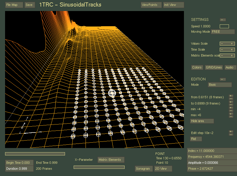
The basic editing features modify the selected field of the viewer at a position determined by the selected point (see figure) and with the + and - keys on the keyboard. An edit step is calculated according to the order of magnitude of the values and can be set using the EditStep + and - buttons in the EDIT area.
To save the changes, use the Save button. Changes not saved before returning to the matrix selection menu or closing the viewer are lost.
It is also possible to edit data in 2D with the mouse on the slice view window (see Slice views).
To edit a larger area, you must determine a set of points on either side of the selected point. Use the corresponding buttons in the EDITING section (The last modified value is then also accessible via the shortcut keys F3/F4). The delimited area can be displayed/hidden with the Sow Area / Hide Area button.
Once the editing surface is fixed, it can be moved by moving the "center" (point of origin, which is not necessarily the center in the geometric sense), or by selecting another point with the mouse.
There are different methods for editing the selected surface. Use the Mode button in the EDIT field to select one of them.
To flatten the editing area, use the Flat button. All the points in the zone will then take the value of the central point (the selected point), which can allow for example to flatten uneven zones.
The data in the figure below will serve as a reference for the examples of each editing mode.

This mode modifies all the points of the surface by the value determined by the EditStep factor.

This mode modifies the points of the zone by applying a factor depending on the initial topology: this method makes it possible to accentuate or soften topological characteristics of the data.

This mode allows you to specify a 3D profile from two B-Spline curves, which will be used as a reference to modify all the points in the zone according to the modifications applied to its central point. The curve editor (see figure) will be used to specify these profiles, by clicking on the EDIT CURVE button. This editor allows you to specify the profiles of the reference editing area.
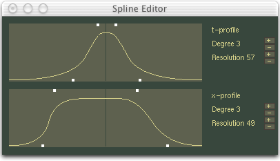
Both curves (editing profiles) of the Spline Editor are calculated from the a set of control points (in white on the figure). By moving these points from left to right, we obtain different profiles. The degree of the curve is also a parameter on which one can play to have more or less marked curves. Finally, the resolution will determine the precision of the form generated. It must be given according to the size of the data area to be edited (at least greater than the number of points in both dimensions). A too low resolution will result in "step" effects, but a very high resolution will slow down execution.
Also note: if the selected point is not really in the center of the editing area (if for example you have chosen to extend it to 10 points on the one hand, and to 20 points on the other), the result will not necessarily be symmetrical like the editor curve but will be expanded, or condensed in one or the other direction.
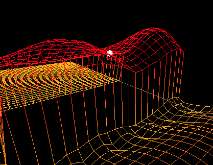
The figure below shows the effect of an edition in Spline Surface mode on the previous reference data.

