Short description of the concept
 The basic concept is to convert an old laptop into compact media-PC that will fit nicely next to TV.
This will be done by removing all unnecessary parts that take up space. These removed parts include atleast the following: display, keyboard, battery, casing and disc drive. Sensor will also be added to detect some light or sound sequence to turn on the PC. The sensor will be connected to Arduino which will in turn drive relay to control the powerbutton embedded in the motherboard.
Description of how you arrived at your design
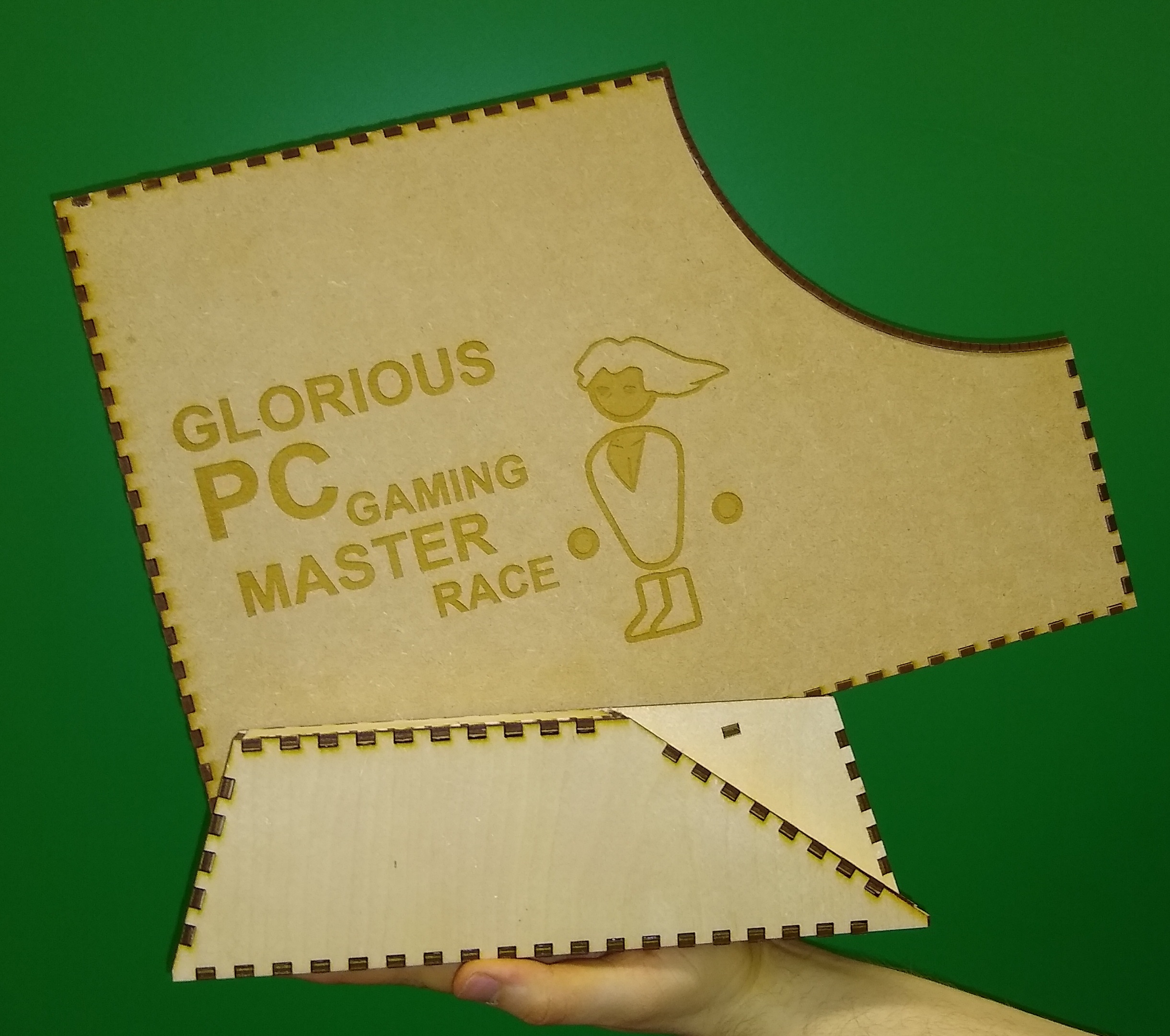
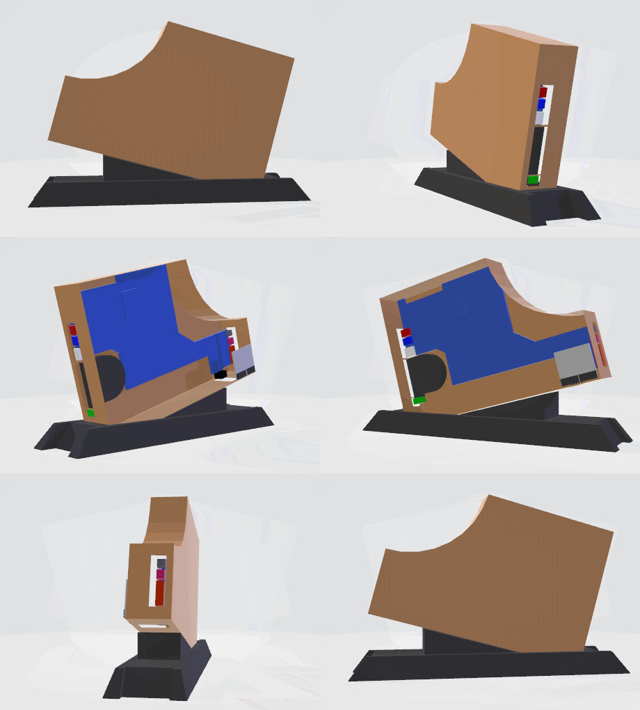 We arrived at the current design by trying to achieve the best performance and asesthetical feeling. The design will use laser cut wood for most parts of the case and move around some components like ports and speakers. Some details are still open such as the exact orientation of the motherboard and how it will be secured to the case. The most promising approach is to use simple extension nuts from hardware store with rubber o-rings to mount the motherboard in place onto the case and create removable panel to access it. Cooling will be done by using existing heat pipe in the laptop in addition to a new fan.
Other options you considered while deciding on your design
 Various other approaches were considered regarding the orientation of components and choice of materials. For controlling the power button we also considered using transistor instead of relay. Using transistor however is more problematic approach as it will require calculating voltages and finding out relative polarities of the connectors.
Bill of Materials
- Plywood for case
- Any Arduino, preferably Pro Micro
- Low voltage relay that can be driven by Arduino
- Additional board that connects to the motherboard, milled at fablab
- Arduino combatible light and sound sensors
- Testing pins to connect additional board to motherboard without soldering
- power button to bypass relay logic manually when needed
NOTE! THE COMPLETE DIARY REPORT IS IN THE WIKI, AS IS THE SUMMARY REPORT
26.2.19
Decided on project idea. Formed group. Started disassembly of the latop (Markus, Atte). Next goal is to finish disassembly and create plans for the case.
01.3.19
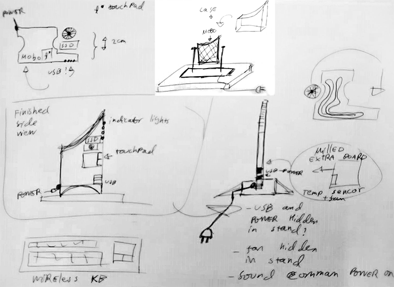
Created first scetches of the project, decided how to actually fullfil the course requirements (Markus, Niko). Next goal is to refine case scetches and finish disassembly
 11.3.19
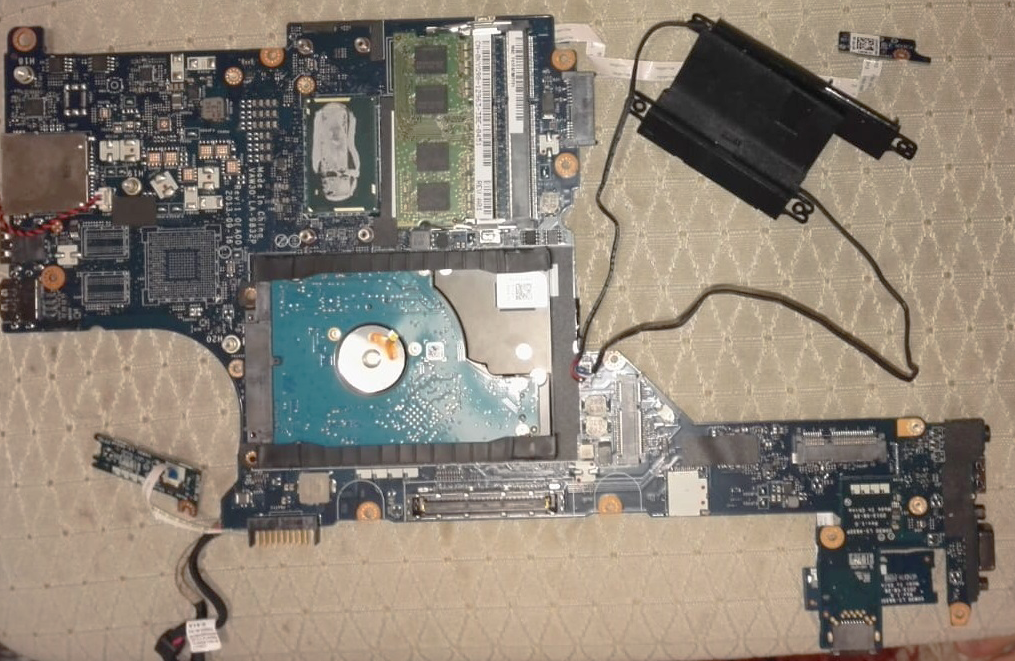
Finished case disassembly. Next steps are to design case that fits the exact dimensions of the motherboard and parts that will be used. Also design needed for powering laptop with relay/transistor (Markus)
 12.3.19
Polished scetches of the case design (Markus, Niko, Veli-matti). Created 3D model for case (Veli-matti). Next step is to finish power button relay/transistor board.
13.3.19
Polished 3D-model (Veli-matti). Designed additional board to control powerbutton with relay/transistor (Markus). Next step is to acquire relay/transistor and build test board.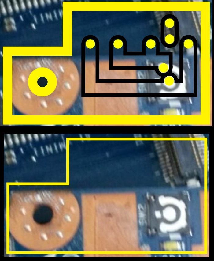
15.3.19
Decided on using relay instead of transistor to control the power button due to transistor not being galvanically isolated (Markus)
17.3.19
Pushed updates into GitHub for this readme. Added pictures. (Markus, Veli-matti)
20.3.19
Made the simulation for the voice control. (Niko) Started working on Arduino code, first version created (Atte, Niko). Polished 3D-model, designed (inkscape) and created first laser cut parts for the case. Created new version of the additional board and started drawing it in inkscape. New additions were transistor to control the relay and diode to limit power-off current from the relay coil. These were due to the 5v power from adrduino vcc being always on so the relay would not power off. Next step on the additional board is to design better system to connect spring powered testing pins to motherboard. Current approach of soldering them on to the additional board won't work since they will be too close to each other for soldering. We are considering on using some kind of holster to hold the pins on place and add wrapped wires instead of soldering. (Markus)
We didn't have any major issues, our only problems were with the simulation (added a breakpoint without realising) and where to find the measurements for the components. Some of the documentation for those components wasn't nearly accurate enough for the project.
21.2.19
Created files for laser cutter and cut holster for spring spikes so that they can be easily held onto the extra board (Markus)
26.2.19
Milled two first versions of board. Both failed (Markus)
Copyleft ![]() Markus Hirsimäki, Atte Viertola, Veijola Veli-matti, Niko Känsäkoski under GNU General Public License v3.0
Markus Hirsimäki, Atte Viertola, Veijola Veli-matti, Niko Känsäkoski under GNU General Public License v3.0