-
Notifications
You must be signed in to change notification settings - Fork 768
Adding a custom wind field to your world
The existing wind plugin in RotorS has been extended to allow the use of a custom, static wind field for a given world. This is done by enabling the wind plugin macro in the aircraft base file (e.g., techpod_base.xacro, which is found in rotors_simulator/rotors_description/urdf), and feeding it the correct parameters and files. The wind grid and values are generated using the fw_planning wind field downscaling model, and are saved in a text file read by the plugin.
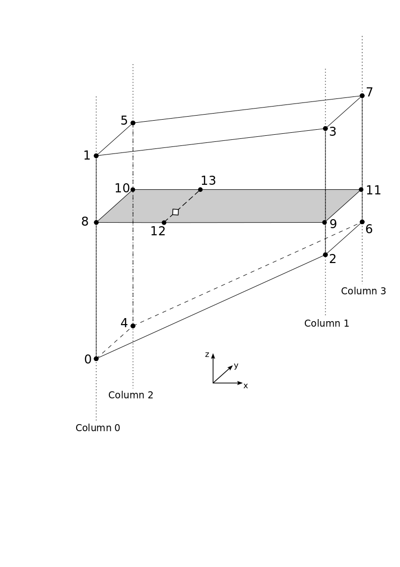
The grid used to define the wind field must be equidistant in x, respectively y-direction. The points in z-direction are distributed with upwards linearly increasing distance (spacing factors can be tuned as desired). The grid is terrain-following, meaning that all the points in the lower z-layer have a constant altitude offset from the terrain.
The text file contains information about the grid geometry as well as the wind values at each grid point. The data needed in the text file consists of:
-
Smallest x-coordinate of the grid
min_x, of type float, in [m]. -
Smallest y-coordinate of the grid
min_y, of type float, in [m]. -
Number of grid points in x-direction
n_x, of type integer. -
Number of grid points in y-direction
n_y, of type integer. -
Resolution in x-direction
res_x, of type float, in [m]. -
Resolution in y-direction
res_y, of type float, in [m]. -
Spacing factors in z-direction stored in
vertical_spacing_factors, an (n_z)-dimensional array of float values between 0 for the lowest and 1 for the highest point. -
The altitude of each grid point contained in the lower x-y plane, stored in
bottom_z, an (n_x * n_y)-dimensional array of float values, in [m].Note: Element [0] is the grid corner point with the lowest x and y-coordinates, and the array is filled counting up in x-direction first, then in y-direction (such that a point with indices i,j corresponds to the (i + j * n_x)-th element of the array).
-
Similarly, the altitude of each grid point contained in the upper x-y plane, stored in
top_z, an (n_x * n_y)-dimensional array of float values, in [m]. -
The x-component of the wind speed for each grid point, stored in
u, an (n_x * n_y * n_z)-dimensional array of float values, in [m/s].Note: Element [0] is the grid corner point with the lowest x, y and z-coordinates, and the array is filled counting up in x-direction first, then in y-direction and finally in z-direction (such that a point with indices i,j,k corresponds to the (i + j * n_x + k * n_x * n_y)-th element of the array).
-
Similarly, the y-component of the wind speed stored in the array
v, and its z-component stored inw.
The order in which the data is saved in the text file is not relevant, but the format must comply with the following requirements:
-
In the first line of the text file, the name of one of the 12 needed data followed directly by a colon (e.g.,
vertical_spacing_factors:) -
In the following line, the corresponding data. If multiple values are needed, they must be separated by a space (e.g.,
0.0 0.025641 0.051282 0.076923 ...) -
The rest of the data follows the same format.
An example wind field text file can be seen for the hemicylindrical world at $(find rotors_gazebo)/models/hemicyl (placed in the same folder as the world model for clarity and convenience).
To visualize the content of the wind field text file, the script visualize_custom_wind_field.py can be used to create a .vtu file, which can then be visualized using Paraview. This is done in three simple steps:
-
Copy the
visualize_custom_wind_field.pyfile into the directory where your .txt file is located. -
cdto .txt file directory. -
Type
python visualize_custom_wind_field.py <input_file_name>.txt. This creates au_vis.vtuand aterain.vtufiles which contain the wind data, resp. the terrain elevation data. These are directly visualizable in Paraview.Note: Paraview can be installed with:
sudo apt-get update
sudo apt-get install paraview
Here is an example of the plugin macro to be added in the base file, containing numerous necessary user-defined variables:
<xacro:wind_plugin_macro
  namespace="${namespace}"
  xyz_offset="0 0 0"
  wind_direction="1 0 0"
  wind_force_mean="0.0"
  wind_gust_direction="0 1 0"
  wind_gust_duration="0.0"
  wind_gust_start="0.0"
  wind_gust_force_mean="0.0"
  wind_speed_mean="5.0"
  use_custom_static_wind_field="true"
  custom_wind_field_path="$(find rotors_gazebo)/models/hemicyl/wind_field_hemicyl.txt">
</xacro:wind_plugin_macro>
All parameters needed in the macro as well as their units are specified in the component_snippets.xacro file.
The four relevant values for the use of the extended plugin are wind_direction and wind_speed_mean, which specify the default constant wind field when the aircraft is flying outside of the custom wind field region, the boolean custom_static_wind_field which, when set to true, enables the extended functionality, as well as the string custom_wind_field_path which describes the path (from ~/.ros) to the text file specifying the grid and wind field.
In brief, the plugin works in distinct steps:
-
Load the plugin and read the text file once, saving the data.
-
During update event:
i. Locate the aircraft and see whether it is flying within the specified wind field bounds.
ii. If so, identify the grid points forming the vertices of the enclosing cell and extract their wind values. If not, set the wind velocity to the user-defined default value.
iii. Interpolate linearly in z, x and y-directions to find the wind velocity at the aircraft position.
iv. Publish the wind velocity in a wind speed message.
