-
Notifications
You must be signed in to change notification settings - Fork 7.4k
New issue
Have a question about this project? Sign up for a free GitHub account to open an issue and contact its maintainers and the community.
By clicking “Sign up for GitHub”, you agree to our terms of service and privacy statement. We’ll occasionally send you account related emails.
Already on GitHub? Sign in to your account
There seems to be some problems in deadtime config of mcpwm (IDFGH-5600) #7321
Comments
About actual behavior
mcpwm_set_duty(MCPWM_UNIT_0,MCPWM_TIMER_0,MCPWM_GEN_B,100);
mcpwm_set_duty(MCPWM_UNIT_0,MCPWM_TIMER_0,MCPWM_GEN_A,duty);
that drives AL to full output and AH about 10% percentage when duty=10.0 About the link to one on hackaday.ioThat is a pretty well example of Operater, Sync and Deadtime submodule. From my perspective all parts function as expected (as figure indicates). But it is not suitable for full bridge driver. About your codeIt must be runtime error when About circuitUsually a H-bridge driver only requires two control wires that each controls a pair of MOSFETs. If it is consist of 4 NMOS then extra circuit is required and must cannot be a "very simple" design. If possible please provide your schematic so that the problem can be addressed quickly. |
|
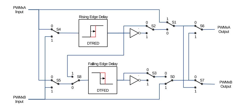
@SalimTerryLi Thanks for your comment! This is my circuit, I think it's enough simple. However, what I want is that I don't want to control the PWMxA and PWMxB, I just want to control one of them, and the other just become inverted signal. The document describe the AHC Deadtime Mode is very similar to what I want.( page 431 in esp32_technical_reference_manual_en) And then I check the picture below, I found that in AHC Deadtime Mode, it just set S3 and S5 =1 ,and other switch set to 0. It means that the source of PMWxB is PWMxb, not PWMxA. Well, so it 's right the result shows that the PWMxb is not the invert of PWMxA, but there is still a problem. According to this picture , because there is a inverter in the out route of PWMxB, so the output of PWMxB should be inverter. When I set the duty 0, it should be high, and when I set duty 100, it should low(duty mode is DUTY_MODE_0). |
|
Thanks for the explanation now I get the idea. AHC doesn't behavior as the API described, that's true. We will find a solution. But I cannot reproduce your condition that PWMxB not being inverted. Here's the captured waveform: PWMxA is continuously outputting 10% duty and PWMxB outputs low when the generator actually started. There is some delay between startup and outputting so PWMxB will output high for about 2ms because of the inverter. RED behaviors correctly and FED cannot be detected due to 100% duty cycle of PWMxB Codes below already make startup time in consideration so no high output will appear on PWMxB: #include <freertos/FreeRTOS.h>
#include <freertos/task.h>
#include "driver/mcpwm.h"
#define H_BRIDGE_A_PIN GPIO_NUM_2
#define H_BRIDGE_B_PIN GPIO_NUM_4
void set_duty(float duty){
if(duty>0){
mcpwm_set_duty(MCPWM_UNIT_0,MCPWM_TIMER_0,MCPWM_GEN_B,100);
mcpwm_set_duty(MCPWM_UNIT_0,MCPWM_TIMER_0,MCPWM_GEN_A,duty);
}
}
void pwm_init(){
mcpwm_config_t pwm_config;
pwm_config.frequency = 1000; //frequency = 1000Hz
pwm_config.cmpr_a = 0;
pwm_config.cmpr_b = 0;
pwm_config.counter_mode = MCPWM_UP_COUNTER;
pwm_config.duty_mode = MCPWM_DUTY_MODE_0;
mcpwm_init(MCPWM_UNIT_0, MCPWM_TIMER_0, &pwm_config);
mcpwm_deadtime_enable(MCPWM_UNIT_0,MCPWM_TIMER_0,MCPWM_ACTIVE_HIGH_COMPLIMENT_MODE,10,10);
set_duty(10);
mcpwm_stop(MCPWM_UNIT_0, MCPWM_TIMER_0);
vTaskDelay(pdMS_TO_TICKS(10));
mcpwm_start(MCPWM_UNIT_0, MCPWM_TIMER_0);
mcpwm_gpio_init(MCPWM_UNIT_0, MCPWM0A, H_BRIDGE_A_PIN);
mcpwm_gpio_init(MCPWM_UNIT_0,MCPWM0B,H_BRIDGE_B_PIN);
}
void app_main(void)
{
pwm_init |
|
@SalimTerryLi Thank you for your time to test. I would try your code later(while because my esp32 board is broken a fews days ago, I could not try it recently). Well, since the inverter behave correctly in yours, some of what I did must be wrong, I would find them. |


Environment
git describe --tagsto find it):4.3
xtensa-esp32-elf-gcc --versionto find it):// 1.22.0-80-g6c4433a
Problem Description
I want to add deadtime for my H bridge driver. I produce 4 pwm signals because my H bridge is juse very simple(there is not a nmos gate driver, and just 4 sot23 Nmos(ao3400)).
//Detailed problem description goes here.
Expected Behavior
what I want is that there are proper deadtime between the AH and AL signals, if possible , just using 2 singals is better( like AL is the reversed phase of AH).
my problem is just like the guy's:
https://hackaday.io/project/169905-esp-32-bldc-robot-actuator-controller/log/184464-mcpwm-with-deadband
Actual Behavior
I set the deadtime mode to MCPWM_ACTIVE_HIGH_COMPLIMENT_MODE, which said "MCPWMXA = rising edge delay, MCPWMXB = compliment of falling edge delay" in comment in code.
and set pwma(AH) = 10, pwmb(AL) = 100 (just close the low bridge) , there seems to produce short circuit.
and I measured the voltage(I have no scope) of AH pin and AL pin, the AH is 0.33v, and AL is 3.3V, which is not I want.
what I want is AH is 0.33V and AL is 0V.
Steps to reproduce
// If possible, attach a picture of your setup/wiring here.
Code to reproduce this issue
When I search the info in the tech document, It shows that the config of MCPWM_ACTIVE_HIGH_COMPLIMENT_MODE (0b001010000 <<8 ) is just close the S3 and S5 of

It should have worked, but I don't know where the problem is in.
The text was updated successfully, but these errors were encountered: