Extreme Wildman Level 3 Certification Rocket
This wiki is to document the fabrication, testing and calculations for a Tripoli Level 3 Certification rocket based on the Extreme Wildman rocket kit.


- Rocket Name: Sigma 3
- Kit: Extreme Wildman
- Length: 113in (modified to use 36" upper tube instead of 24" tube)
- Diameter: 4in
-
Motor 1: CTI K1085WT, 75mm 2-Grain
- Total Rocket Weight (with motor): 383oz
- Average Thrust: 1085
- Thrust to Weight Ratio: (243.91 pounds)/(383oz/16) = 10.18
- Simulated Apogee: 5529ft
- Simulated Max velocity: 663ft/s (About Mach 0.6)
- Velocity off 6ft Rail: 58.7ft/s
- CG: 74.91in
- CP: 93.911in
- 4.72 Calibers
-
Motor 2: CTI 5506M1230-P, 75mm 4-Grain
- Total Rocket Weight: 468oz
- Average Thrust: 1229.6N
- Thrust to Weight Ratio: (276.4 pounds)/(468oz/16) = 9.44
- Simulated Apogee: 13298ft
- Simulated Max velocity: 1191ft/s (About Mach 1)
- Velocity off 6ft Rail: 62.5ft/s
- CG: 78.662in
- CP: 93.911in
- 3.79 Calibers
- Altimeter 1: ARTS-2 (main)
- Altimeter 2: TeleMetrum (backup)
- Parachute: 10ft Rocketman Standard Parachute
The rocket will be based of the "Extreme Wildman" kit, which has fiberglass tubing, 3/16 G10 fiberglass fins, fiberglass nosecone with aluminum tip. A 2ft diameter drogue parachute will be used, with a 10ft diameter main parachute. I'm targeting a decent rate under the main of 20FPS, and a decent rate under drogue of somewhere between 65FPS and 100FPS.
Full Bill of Materials and Checklists
- West System 105/205 Epoxy will be used throughout rocket
- All structural fillets will be reinforced with chopped carbon fiber
- Anti-zipper mechanism will be used on shock-cords
- 5/16 Rail buttons will be used, suitable for 15/15 rail at OROC launch
- Sets of (3) 2-56 nylon shear pins will be used
- 1/8" vents in the body tubes
The rocket will use a RocketMan 2ft diameter standard parachute for the drogue, and a RocketMan 10ft diameter standard parachute for the main. You can see a table of decent rates on the rocketman web site: Parachute Decent Rates
The main altimeter will be configured to deploy the drogue 0.5 second after apogee, and the main at 1000ft AGL. The backup altimeter will be configured to deploy the drogue 1.5 seconds after apogee, and the main at 800ft AGL.
Assembly procedures will largely follow the instructions from Wildman Rocketry, Extreme Wildman Instructions . These procedures are tested and proven and known to work well.

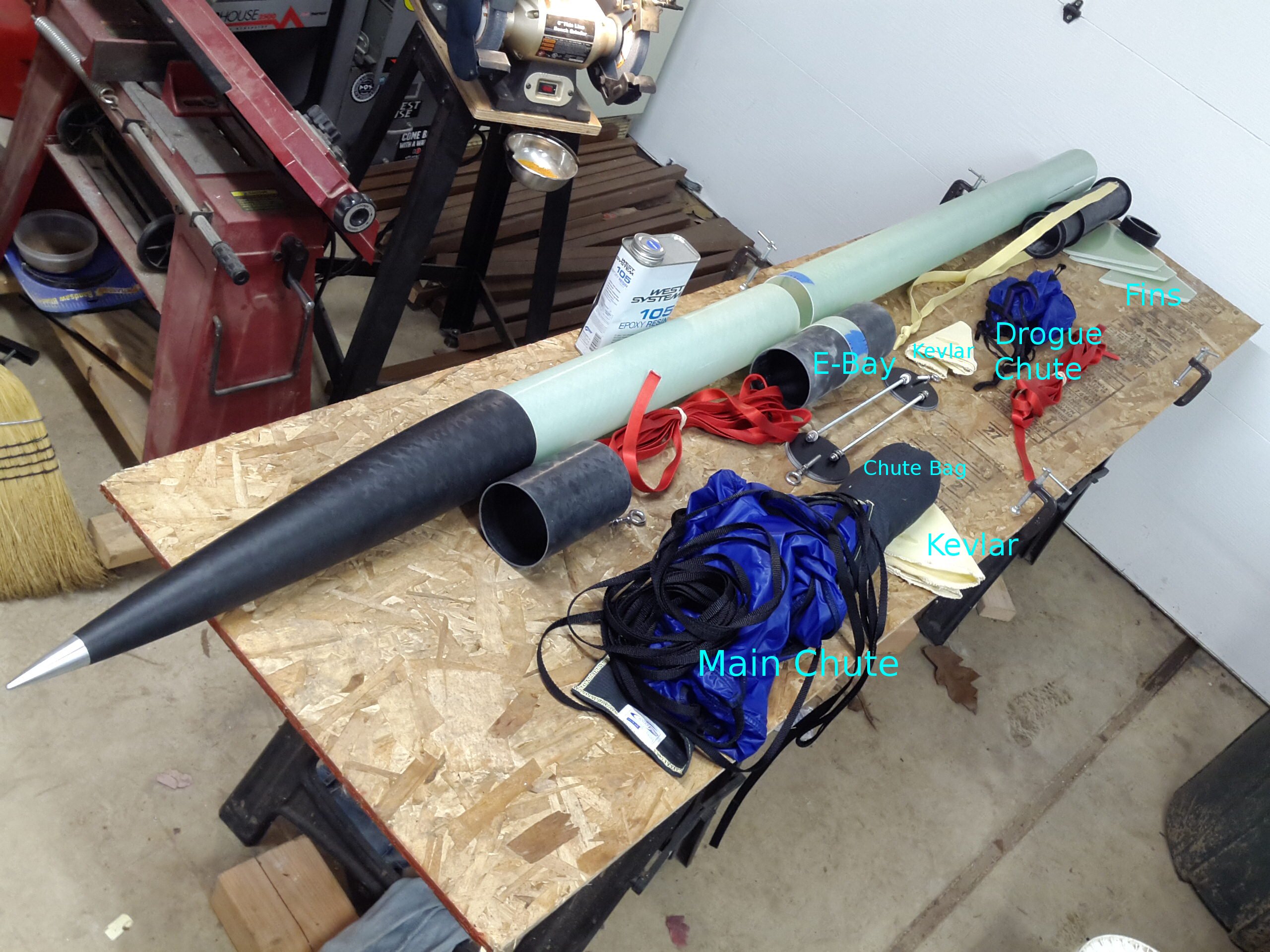
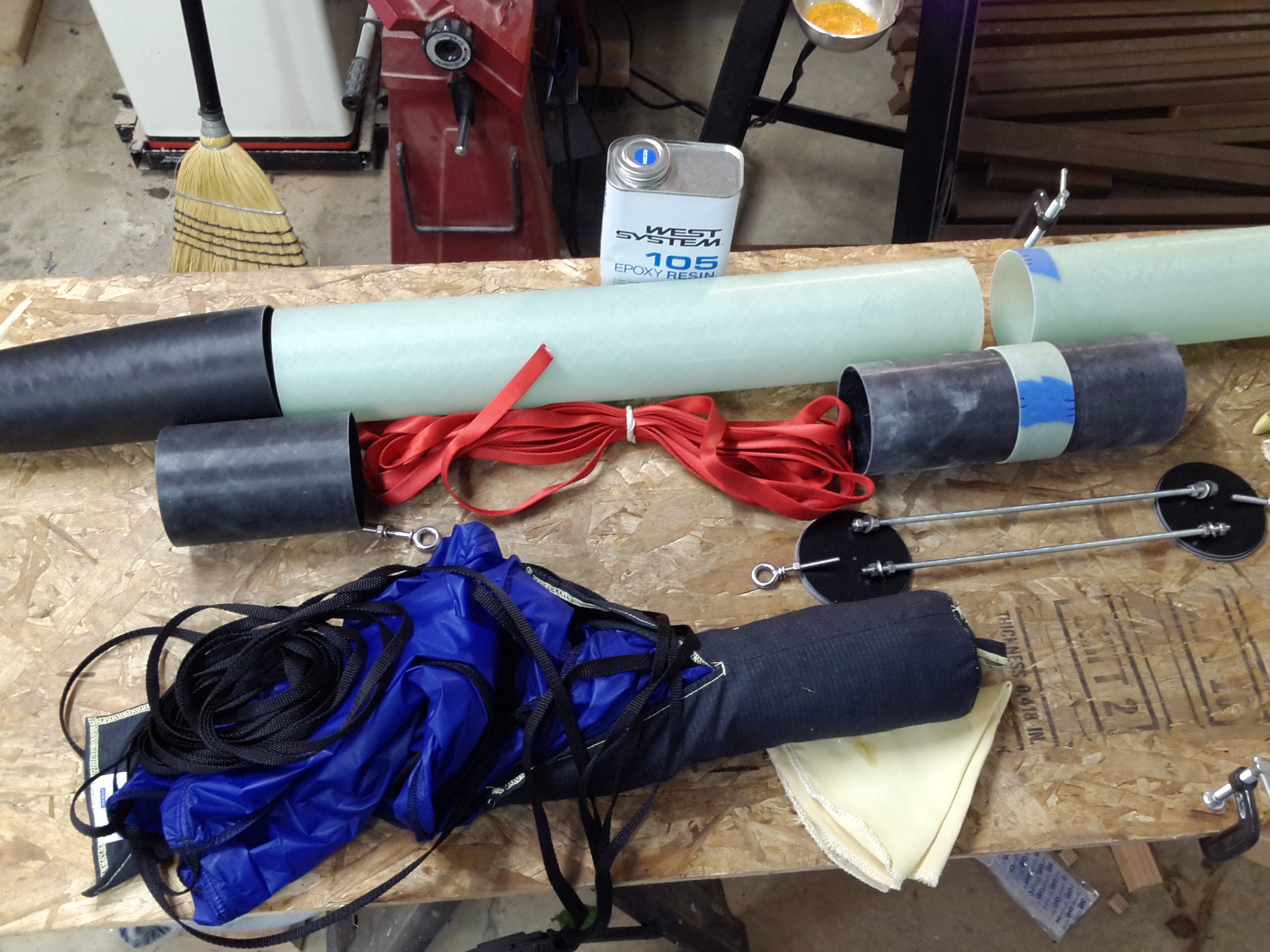
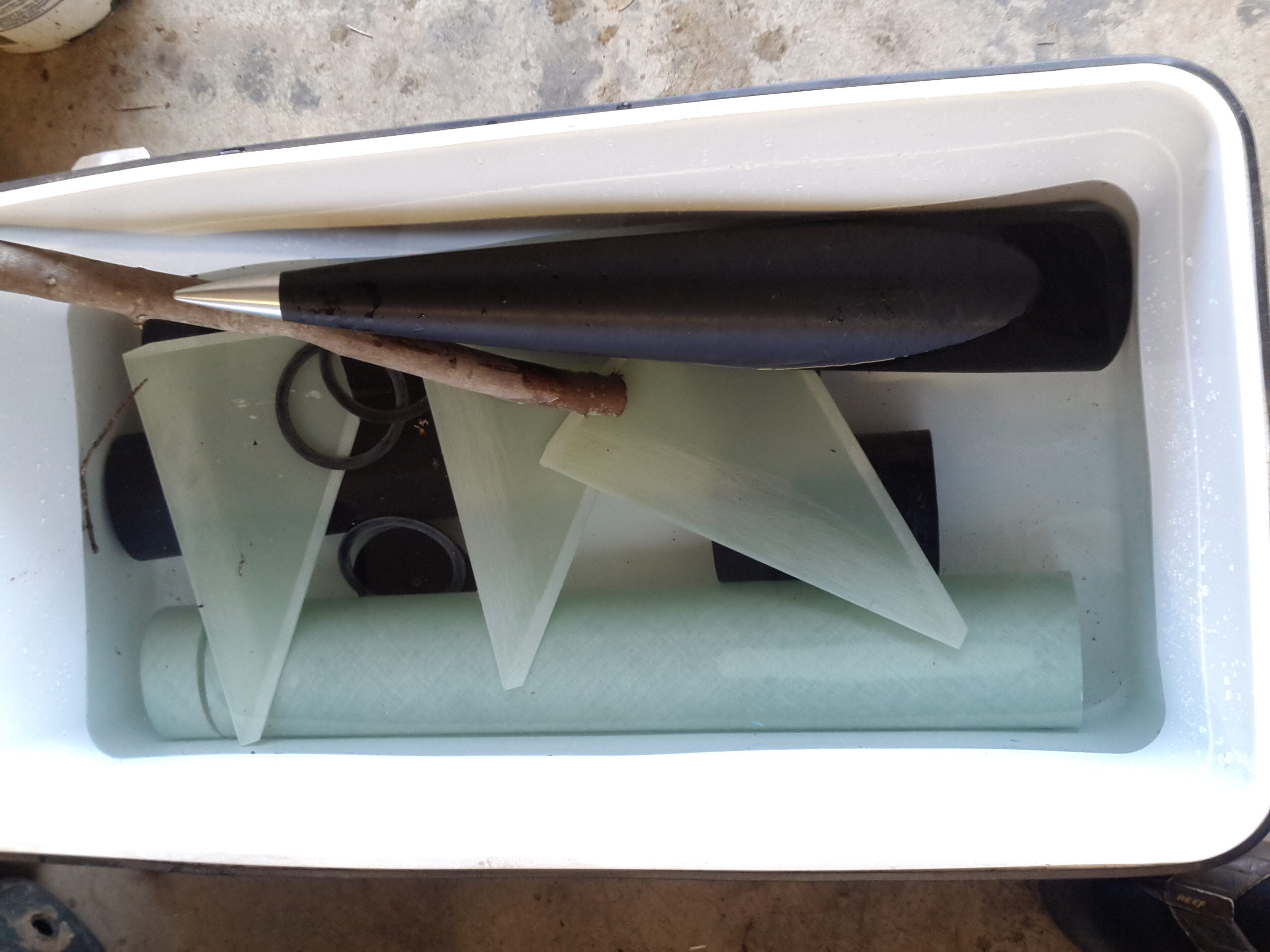
These photos show the layout of the various components, before actual assembly.


Fiberglass parts were soaked in water for 24 hours to dissolve any remaining mold release agent on the fiberglass.

Eye bolts are 1/4-20 Stainless Steel, which came with the kit, with a top hex nut, a bottom hex nut that is tightened against the lower half of the bulk head, then a nylon-lock nut that is tightened as a jam-nut against the lower hex nut. This is over-engineered, but will provide plenty of strength and avoid vibrating loose.
The upper bulkhead use two semi-permanent nylon lock nuts on the all-thread. There should be no need to remove these lock nuts. The lower bulkhead has a pair of hex nuts in a jam-nut configuration for the interior half of the bulk head, and the upper side of the bulk will had a normal hex nut to tighten it down. It is expected that from time to time the avionics sled will need to be removed, and it's very easy to 'break' the jam-nut configuration and remove all the nuts with only fingers. The upper side of the bulk head specifically avoids wing nuts as they are critical load bearing nuts and I don't like wing-nuts for critical applications. I may also setup the upper nuts in a jam-nut configuration, or possibly use a lock washer.


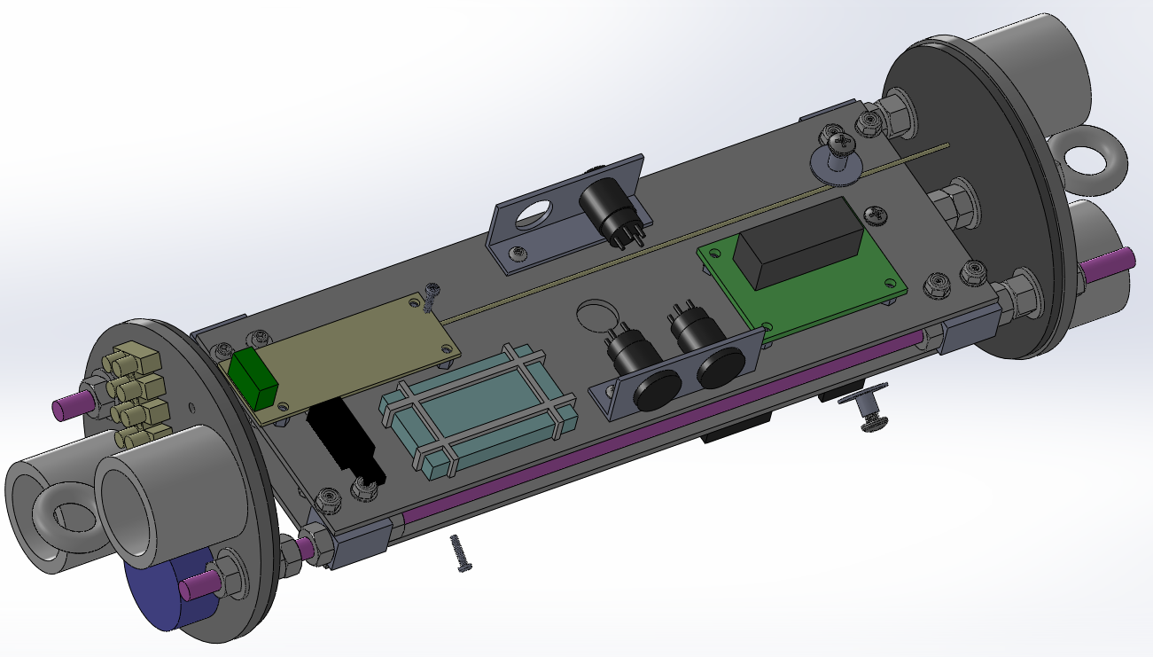
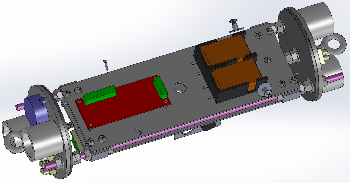
Below are CAD models of roughly what the electronics sled will look like.


I printed out a drawing of the sled plates at a 1:1 scale, then taped them to the fiberglass, traced the edges, then used a spring-punch to transfer the hole centers to the underlying fiberglass. I cut the fiberglass using a diamond blade on a table saw, and drill the holes where the punch had left location marks.
I took some aluminum and milled it down to the dimensions that I wanted, then drilled holes for the rotary switches and 4-40 mounting screws. I milled down some aluminum flat bar to make the 4 corner blocks that slide over the 1/4-20 threaded rod.


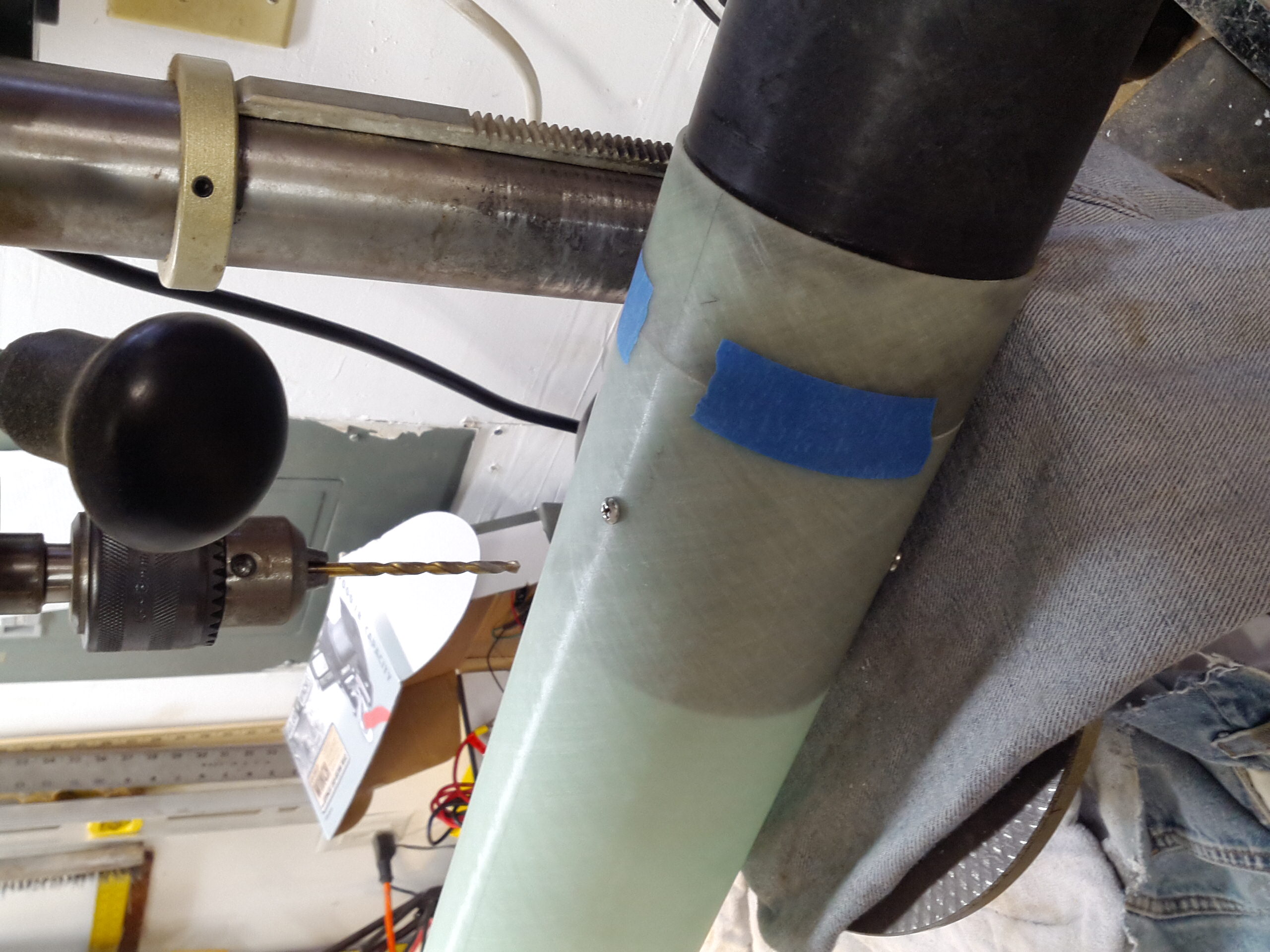
I fit and located the upper tube onto the e-bay tube, then taped it in place. Drilled the first hole then installed the screw to make sure it didn't rotate while I was drilling the other 2 holes. I epoxied the T-Nuts in place on the inside, then set the whole assembly on top of the lower tube, made sure to align it properly with the mid-fin, such that when the telemetrum is installed it will be facing forwards, taped it, and drilled holes for the shear pins. I found that it was easiest if I just mashed the shear pins into the holes. Trying to screw them into place didn't really work. To manually remove them, I ended up clipping the head off and pushing them through the hole with a punch.


Below is the schematic for the electronics bay. Rotary switches are used in a double-contact configuration to minimize the possibility of power glitches due to contact vibration during flight. Molex 4 and 8 pin keyed/locking connectors are used. This insures that it's mechanically impossible to connect things incorrectly while in the field. A buzzer circuit was added to this to ease locating the rocket in the field in the event that GPS coordinates are not available from the Telemetrum.

A mixture of epoxy and chopped carbon fiber will be used for structural bonding of fins, main tube, motor tube and centering rings. The interior fillets between the fin root and the motor tube will be done via the injection method. Following that, exterior fillets will be added between the fin and the main motor tube. Some fillets will also include colloidal silica as a thickener based on the Wildman instruction manual.


Locating lines were drawn along the length of tubes in various places, including a line for the rail buttons, lines for where the shear pins will intersect, and lines for where the vents should go.


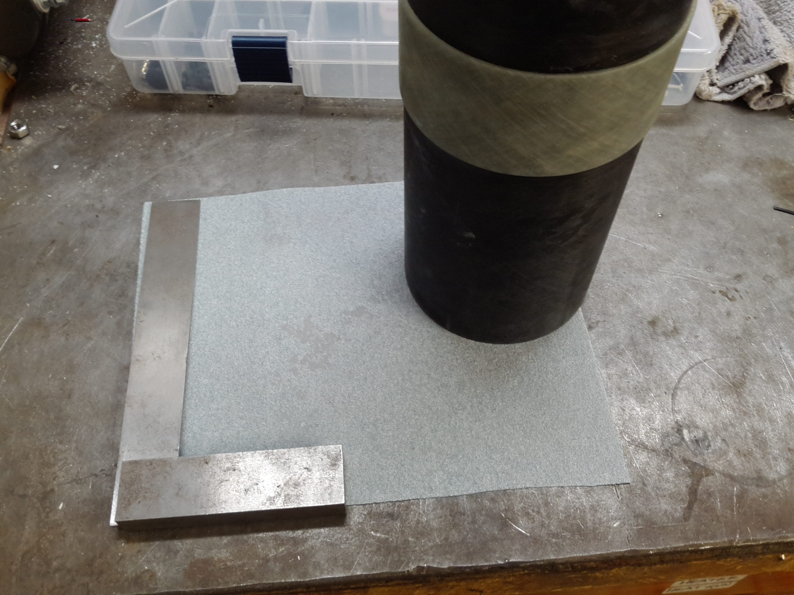
The tube ends were not quite square, which was causing alignment issues when butting the ends to each other on the E-Bay and for the motor-to-slimline face and the e-bay bulk plates. I used a square to figure out which side was "high", and put a piece of 80-grit sand paper on a flat surface and sanded the end, pushing harder on the high side then the low side. I did this over a few iterations, sanding then re-checking until it was pretty much square.
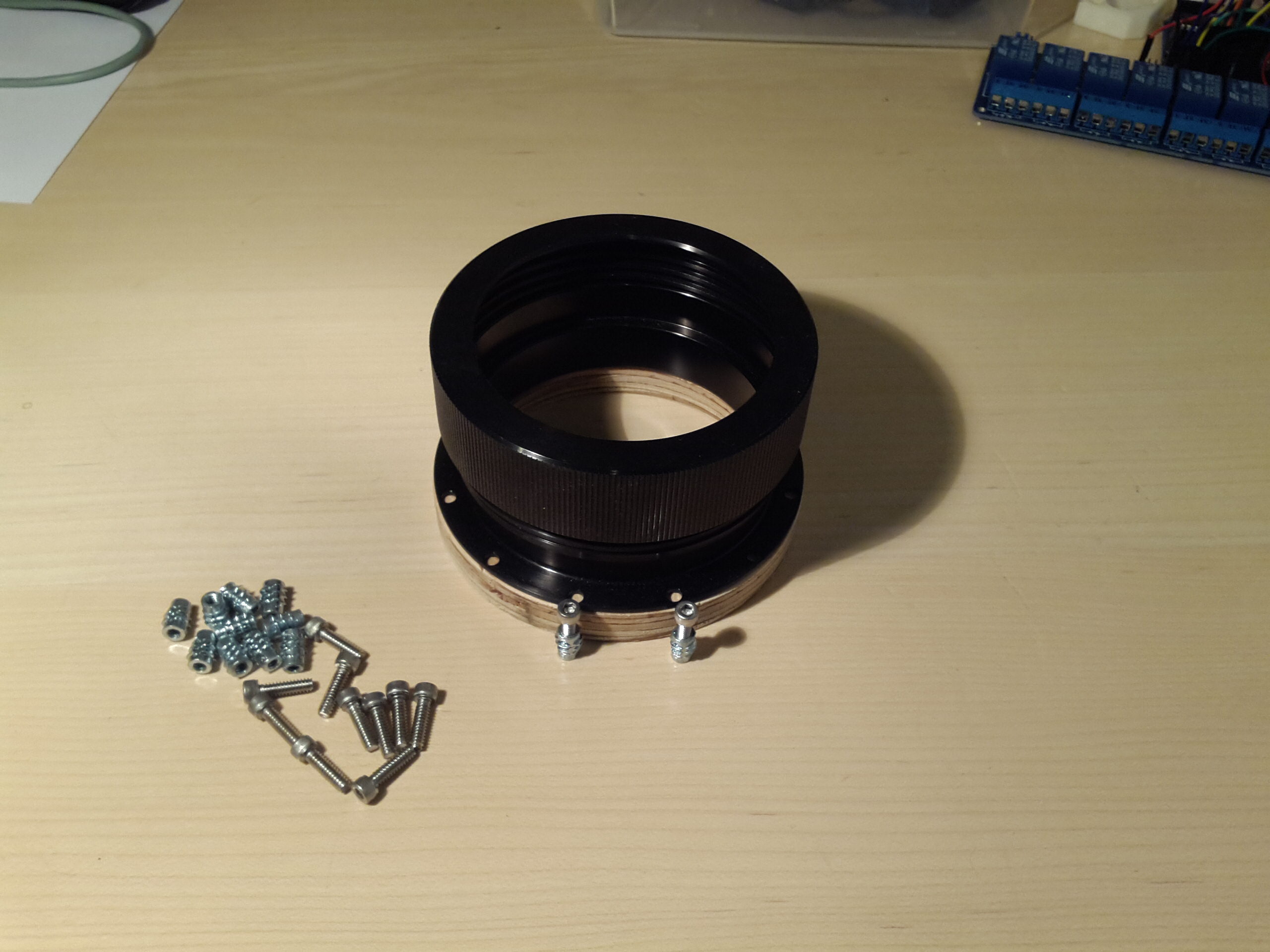
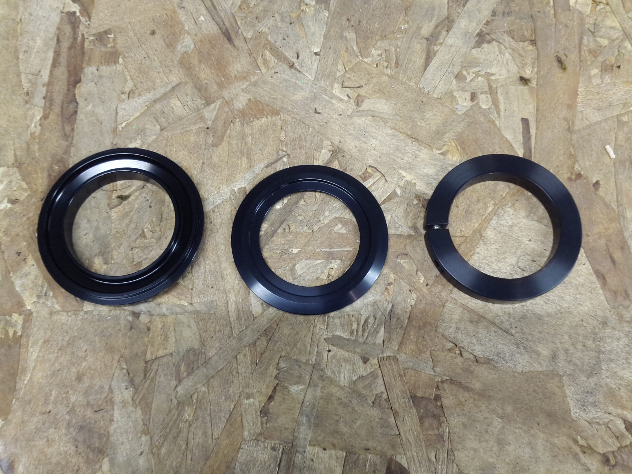
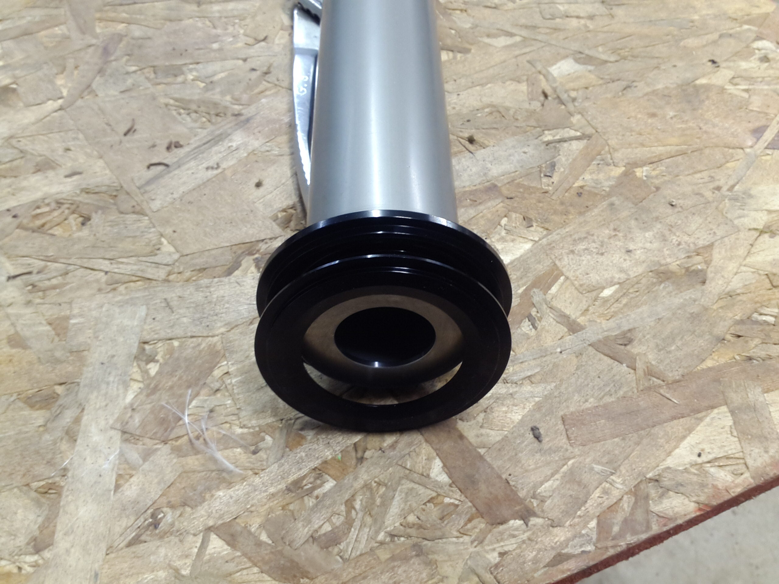
A slimline motor retainer will be used to retain the motor. An additional plywood centering ring was made to sit just below the lowest centering ring on the motor tube. That plywood will be drilled and machine threaded inserts screwed in, allowing for the slimline screws to be threaded into those and securely mount the slimline to the bottom of the rocket.

The 5/16" 1515 rail buttons will be affixed via 10-24 steel machine screws. The 1/4" 1010 rail buttons will be affixed using 8-32 steel machine screws. T-Nuts will be epoxied in place on the inside wall of the tube. Two different thread pitches will be used in each location to accommodate rail buttons for both 10/10 and 15/15 rails.


I buried the T-Nuts for the rail buttons in epoxy on the inside diameter of the fin tube. I tightened up the screws from the outside to hold the t-nut in place, let the epoxy cure, then unscrewed the screws and cleaned up the hole a bit by hand. For the upper T-Nut, I went ahead and drilled the vent hole directly opposite the T-Nuts, thus allowing me to use the injection method to gravity-drop the epoxy into the backside of the upper t-nuts. Again, I used masking tape to make a dam on either side of the t-nuts to hold the epoxy in place. This will will be sanded such that there is a contour going into the inside wall of the fin tube, as I don't want cords or the parachute to snag on anything. Make sure to epoxy the tail t-nuts in place after putting the motor tube in, otherwise the epoxy will interfere with the motor tube centering rings.
I found it difficult to create a contour on the middle chunk of epoxy, so I made up some thick 15 minute hobby epoxy, and put a blob on the edge and set the tube at a 30 degree angle such that the blob would flatten out and create a contour. Let that set and flipped it over to do the other side. The technique worked great and there is a nice smooth finish for it.


The recovery harness was epoxied to the outside diameter of the motor tube and buried in epoxy to provide additional mechanical support. This much epoxy is probably a bit excessive, but meh, I had the epoxy and I don't care about weight...


For fin alignment during epoxying, I generated a paper alignment guide from http://www.payloadbay.com/index.php and used spray adhesive to affix it to a piece of plywood. I then used a table router to route out the center, and screwed in 2x4's from the bottom.


To tack the fins in place, a bead of epoxy was run along the motor tube and the root of the fins, the fins were inserted into the tube, rear centering ring put in placed, the fins were clamped such that they were pushed up against the motor tube on the jig and let cure. To confirm, fin tip-to-tip measurements were taken and all of them came out to about 1/32" of an inch of each other, indicating that they were indexed almost exactly 120 degrees from each other as we want. A small amount of epoxy was used on the rear CR to make sure it was sealed up. This was then sanded in preparation for the wood centering ring.


A mixture of epoxy and chopped carbon was injected into the cavity between the fin tube and the motor tube. It was held at alternate 45 degree angles to get the epoxy to flow up and down the length, then leveled in both planes and let to cure. The epoxy wanted to slowly ooz out of the injection holes (which also indicated that it was full internally), so tape was placed over the holes to slow the rate of oozing.


The rear wood centering ring was drilled, and the screw inserts screwed in. The outside of the wood ring and inside pocket at the end of the rocket was coated and shallow filled with epoxy, thus forming a small bath of epoxy. The entire ring was placed in place. The motor was put in and clamped down to ensure that the edge of the motor was in plane with the slimline retainer so that forces would be evenly distributed over the face of the retainer.


External Fin Fillets


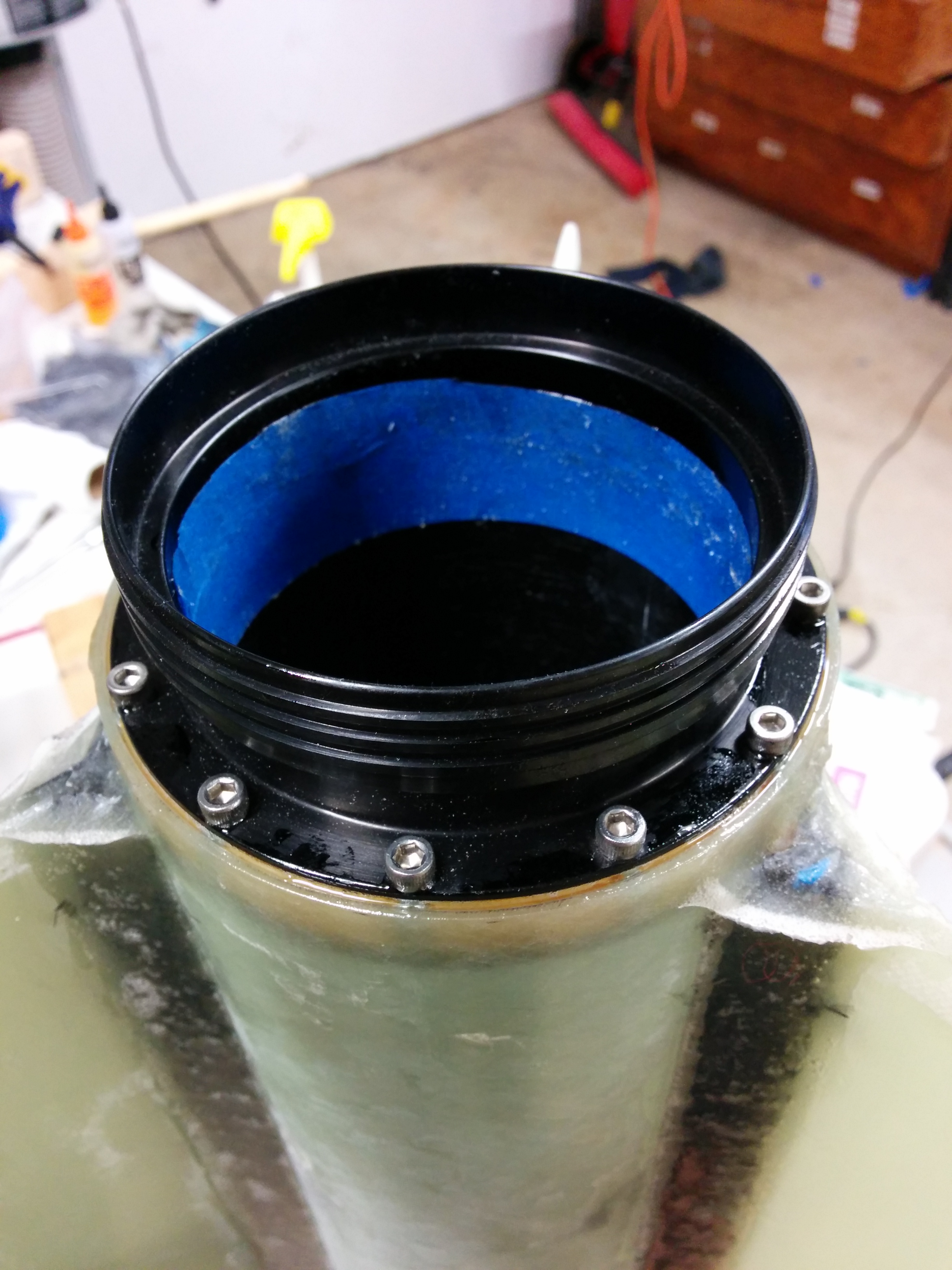
The nose cone was built to allow some extra space above the parachute for the shock cord. I epoxied the two bulk plates together, then let the epoxy squish out the edges of the plates and affixed it to the top of the coupler. Let that cure, and epoxied it into the nosecone itself. I drilled a small vent hole in the bulk plate to allow for air transfer while I inserted the coupler into the nosecone itself. After that cured, I added additional re-enforcing epoxy to the interior of the coupler.


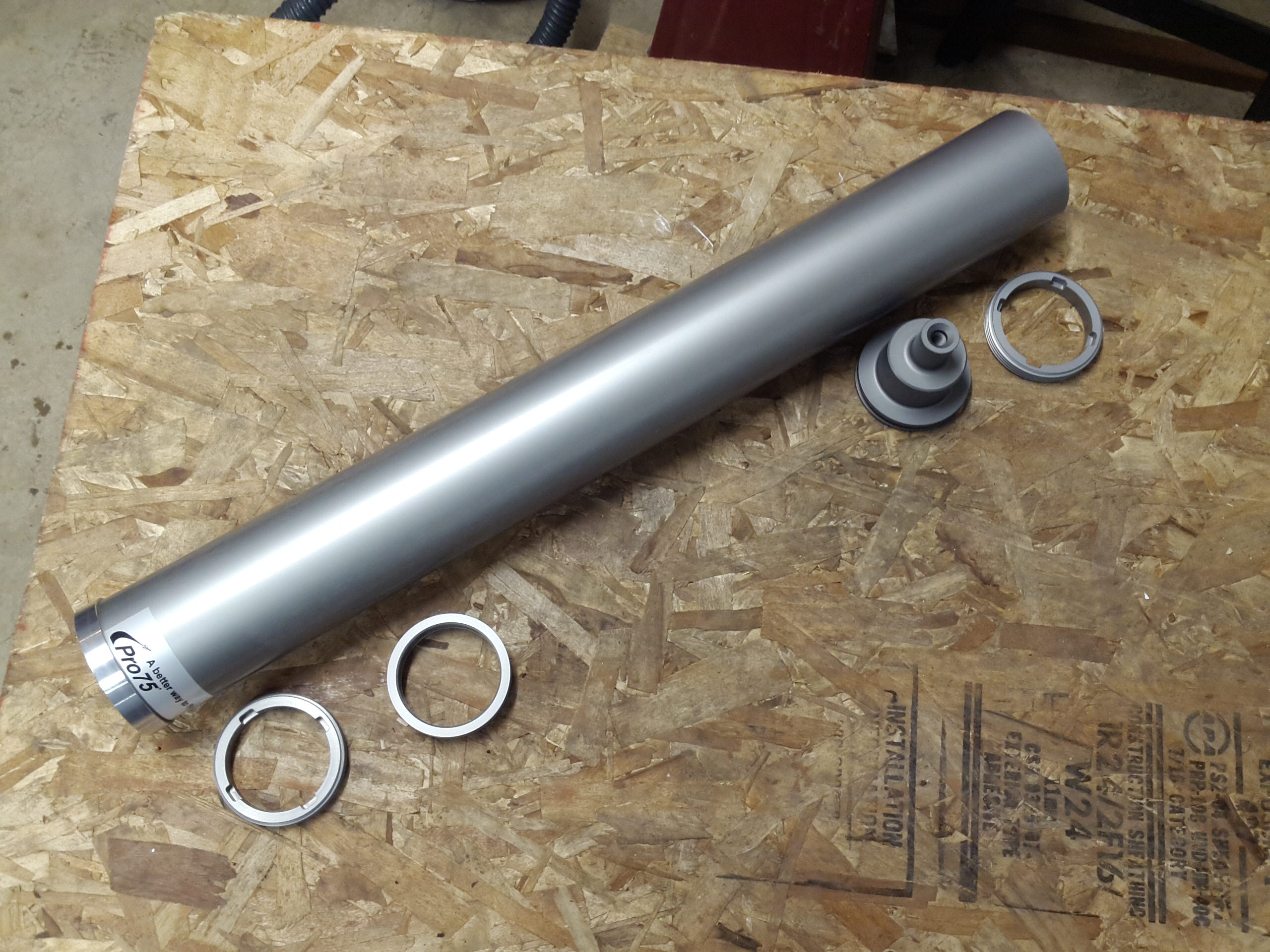
75mm and 54mm Motor Casings. An Areopac 74mm to 54mm adapter will be used for an initial test flight of the airframe on the K motor.


The 2ft drogue parachute will be deployed at apogee. This parachute will be dragged out of the tube. It is small, and will be very lightly packed, and should come out with no problems.
The rocket will descend, to about 1000ft above ground level, at which point the 10ft main parachute will deploy. This will be blown-out. It's packed tighter then the drogue due to it's size, and the BP charge well will be under it (with a Kevlar cloth between them of course), and it will pressurize the tube, shear the 2-56 shear pins, and blow the whole parachute out.
[ ]
(images/parachutes.png)
]
(images/parachutes.png)
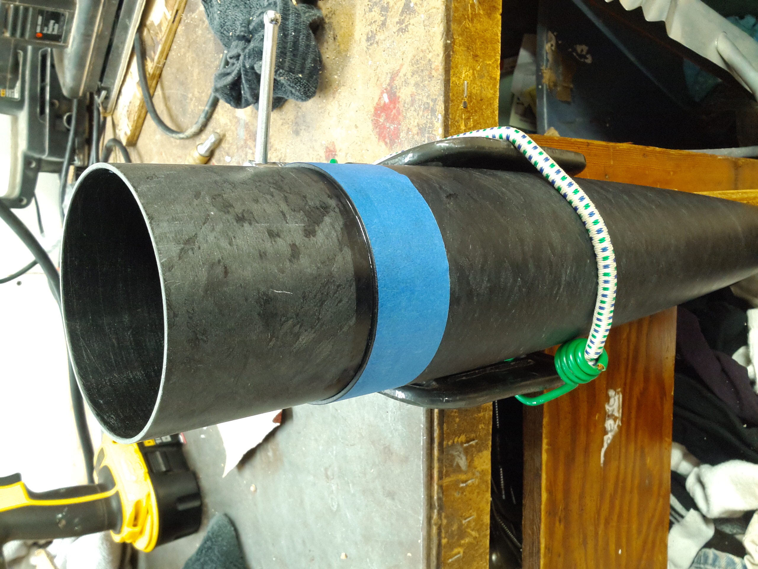
To fire the pyros remotely, I connected a pair of wires inside the E-Bay to where the flight computer would normally connect to the charge-well wires. I then fished the wire out the switch holes on the side of the E-Bay. I chopped the end of a power cord and stripped two of the wires, then clipped alligator clips on to it, then took my 100ft extension cord and plugged it into the hacked cord. The prongs on the other end of the extension cord were perfectly aligned to simply touch a 9V battery to the prongs and provide current to the e-match in the charge well. In order to maintain pressure in the drogue cavity, I had to custom cut a 2x4 and put it in the motor casing and tighten it up. I also had to put screws in the holes for the launch lugs, otherwise it would vent pressure to the outside when they fired.


I measured out the exact weight of BP that was called for on each test using a jewelers scale. I happened to have some old chemistry tools from my childhood chemistry kit, which came in handy for this.


Drogue Testing
Drogue Testing went as planned. Of particular note, in the slow motion video, you can see the light from the BP charge going off through the tube just before the tubes separate. Super cool!
- Test 1: 2.1g BP, worked as expected
- Test 2: 2.8g BP, worked as expected
- Test 3: 3.02g BP, worked as expected


Drogue testing photos:


Main Testing
The main parachute ended up being packed too tightly in the upper tube. After putting the e-bay in, the tube simply doesn't have the necessary cubic volume to hold the chute and bag loosely. This requires a minor design modification. The standard 24" tube will be replaced with a 36" tube to allow for packing the parachute loosely, and make it easier for the main parachute to come out and avoid getting stuck.
- Test 4:, 1.4g BP, 24" tube, failed to fully pull chute bag from tube
- Normal Speed Video: https://github.com/dsigma/l3_rocket_certification/wiki/images/video/
- Slow Motion Video: https://github.com/dsigma/l3_rocket_certification/wiki/images/video/

- Test 5:, 1.97g BP, 24" tube, failed to fully pull chute bag from tube
- Test 6: 2.92g BP, 36" tube
- Test 7: 3.89g BP, 36" tube
- Test 8: 3.4g BP, 36" tube


Failed deployment on tests 4 and 5 using the 24" tube and the parachute bag. I believe that the deployment bag would be more suitable in a larger diameter airframe. Trying to cram it into a 4" tube is just not a reliable way to deploy a 10' parachute.


Recovery Testing with 36" Upper tube, tests 6-8. I stopped using the deployment bag as it just did not seem reliable. For the test, I used an old shop rag in place of what will be a large piece of nomex or Kevlar cloth, but was suitable for testing purposes.


Final BP Charge Selections
- Drogue Primary: 2.8g
- Drogue Backup: 3.0g
- Main Primary: 3.4g
- Main Backup: 3.6g
I did a light sanding on the whole airframe, and filed off any minor epoxy protrusions, then primed and painted with gloss paint. Note: Make sure to cover the sleeve surfaces with tape/paper as the additional thickness of the paint will cause problems with the recovery system deployment and general assembly


Open Rocket simulations can be download from https://github.com/dsigma/l3_rocket_certification/blob/master/Wildman_Extreme_openrocket.ork
[ ]
(images/L3_OpenRocket_Simulation_Screenshot_1.png)
]
(images/L3_OpenRocket_Simulation_Screenshot_1.png)

[ ]
(images/L3_OpenRocket_Simulation_Screenshot_3.png)
]
(images/L3_OpenRocket_Simulation_Screenshot_3.png)
Matlab code to calculate ejection charge:
airframe_diameter = 4.0  %inches
airframe_radius = airframe_diameter / 2.0;
number_of_shear_pins = 3
shear_force_per_shear_pin = 35  % approx 35 pounds to shear a 2-56 nylon screw


%%%%%%%%%%%%%%%%%%%%%%%%%%%%%%%%%%%%%%%%%%
%Calculations for BP charge sizes
%
%From http://www.info-central.org/?article=303
%C * D * D * L = grams of BP Where:

%C - one of the values listed below
%0.002 = 5 psi
%0.004 = 10 psi
%0.006 = 15 psi
%0.0072 = 18 psi
%0.008 = 20 psi
%D = airframe diameter, in inches
%L = length of the cavity to be pressurized, in inches

charge_psi = 17;
C = 0.0065;  %from table above
D = airframe_diameter;    %inches
Lmain = 36.125 - 5.0 + 5.5;   % inches, compensate for the E-bay and nosecone
Ldrogue = 52.0 - 7.0 - 18.0; %inches, compensate for E-Bay and Motor


main_grams_of_bp = C * D * D * Lmain
drogue_grams_of_bp = C * D * D * Ldrogue

% The number of pounds over the expected shear force
% necessary for all the shear pins
ejection_force_necessary = (number_of_shear_pins * shear_force_per_shear_pin)
charge_force = (pi() * airframe_radius^2 * charge_psi)
charge_pressure_factor_of_safety = charge_force / ejection_force_necessary
Output of code
airframe_diameter = 4
number_of_shear_pins = 3
shear_force_per_shear_pin = 35
main_grams_of_bp = 3.8090
drogue_grams_of_bp = 2.8080
ejection_force_necessary = 105
charge_force = 213.6283
charge_pressure_factor_of_safety = 2.0346
Based on the calculations above, I'll need 3.8g of BP for the main charges, and 2.8g of BP for the drogue. This are purely theoretical numbers. This will have to be backed up by empirical testing and adjusted based on real-world test results.
Note: I double-checked these calculations using the web-based calculator at http://www.info-central.org/?article=303 .
I figured it would be easier to pre measure my charges at home and put them in small containers before heading out. Given that things will be busy in the field, and messing with scales and powders and cross winds, this seems much more practical and less prone to error. I found some 1/4oz plastic containers on e-bay that worked perfectly for this!


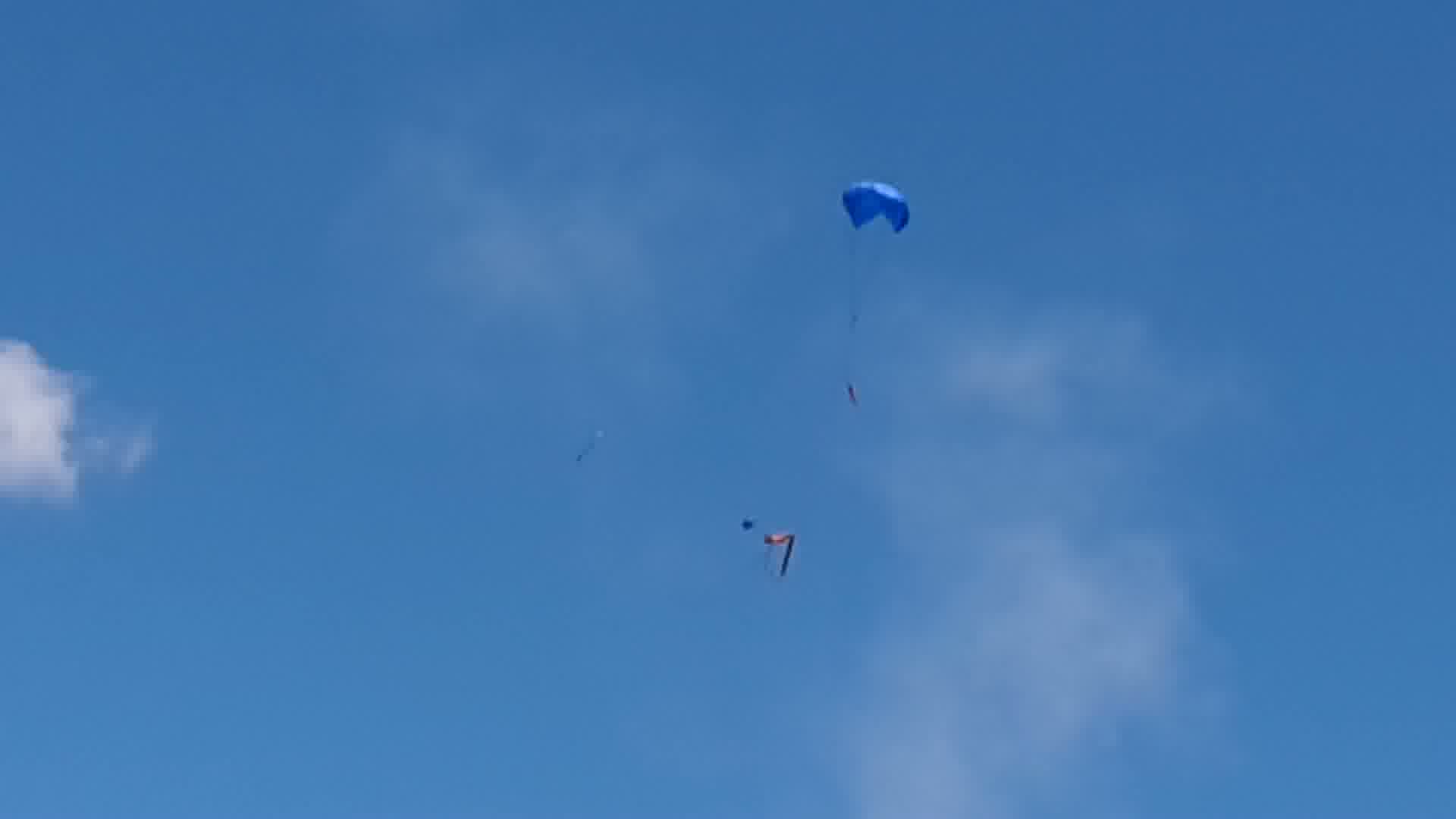
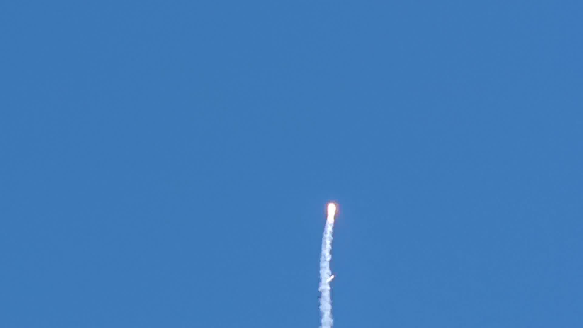
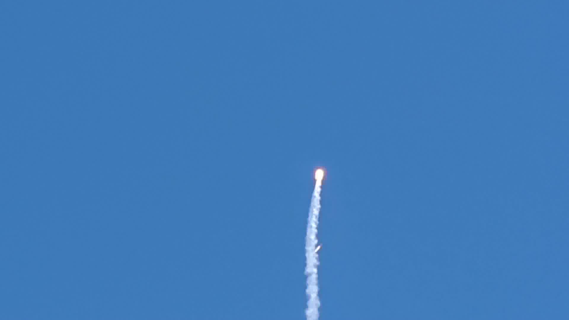
Unfortunately, shortly after liftoff the CTI K940WT motor CATO'ed. The top end of the motor casing failed, causing the cavity to pressurize, there separating the lower end of the rocket from the E-bay and sending the lower section flying past the upper section. The drogue chute came out, and the lower portion was something of a rocket torch for a short period of time. This was enough to cook the interior of the rocket, burn through the Kevlar strapping that was epoxied to the motor tube. On the tube, you can see next to where the casing came apart, that the paint is cooked on the outside of the rocket body. The sticker on the top end of it is also cooked.
The lower section of the rocket came down sideways, an while it was coming down developed a high speed axial spin. When it hit the ground, due to the spin, the red fin hit hard enough to completely bust it apart and out of the tail end. During the spin, the shock cord wrapped around the tube of the rocket, and somewhere in that time was tight enough to damage the side wall of the tube and cause a significant structural comprise. The damaged part where the shock cord wrapped was kinda soft to the touch. This was also strong enough to break the shock cord (which actually may have been compromised anyways by the jet of motor flame going across it from the top of the motor.
On the plus side, the rest of the rocket worked as expected! The upper half of the rocket reached apogee (maybe 100 feet?), fired the pyros for the drogue, then fired the pyros for the main chute, which cleanly deployed and brought the top half of the rocket down softly...
I contacted CTI about the CATO and provided pictures. They said that there was a batch of 54mm forward closures that were defective and that this looked similar to other 54mm motor failures that they had seen in the past. The issue has since been corrected on their end, and they are providing warranty replacement of the casing and reload. I found the warranty process to be easy, and the folks at CTI were very nice to work with.
M1230 Motor Assembly


Prep


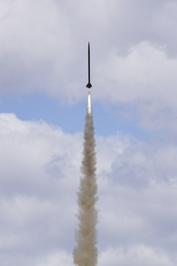
Pad


CATO!


Gary Gonchers' Photos, nice pictures Gary!


Normal Speed Video Snapshots


High Speed Video Snapshots


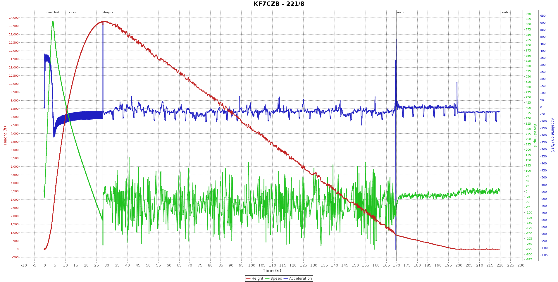
Telemetrum Data


ARTS2 Data

I decided to do things a little differently this time around. My rocket was a bit heavy on the first build, so I decided to be more conservative with the epoxy. I still loading the epoxy where it makes structural sense, but I'm omitting the large quantity for the Kevlar straps. I'm also going with just 10/10 rail buttons this time. OROC, the group I'm launching with, has like 8-10 of these rails, and 10/10 is just fine for this rocket. Other then that, everything else will be the same.


Slow Motion Video: https://github.com/dsigma/l3_rocket_certification/wiki/images/video/20140704_Recovery_Test9_Slow_short.avi
- Altitude: 13796 ft
- Max Velocity: 815MPH (Mach 1.1)


Gary Gonchers' Photos


Gary Gonchers' Photos
TeleMetrum Data


ARTS2 Data

