Version 2 Paths
The SQUARE, CIRCLE, and TRIANGLE primitive shapes are implemented as lists of path operations, which are drawn on a canvas. The new path feature allows new primitive shapes paths to be defined. A path contains a list of path operations and path commands. Paths are defined to support the path drawing features found of SVG files and the OpenVG specification.
The simplest path is a path sequence followed by a path command. The path sequence specifies where to draw and the path command specifies whether to fill the path sequence or stroke it. A path sequence begins with a MOVETO to set where the drawing part of the path starts, some number of path operations (LINETO, CURVETO, ARCTO) that specify the path for drawing, and an optional CLOSEPOLY that causes the path sequence to return to the its beginning (i.e., the MOVETO). Here is a simple path:
path box {
    MOVETO{x 0.5 y 0.5}
    LINETO{x -0.5 y 0.5}
    LINETO{x -0.5 y -0.5}
    LINETO{x 0.5 y -0.5}
    CLOSEPOLY{}     // go back to (0.5, 0.5) and close the path
    STROKE{}        // draw a line on the path using the default line width (10%)
}
There are a couple of ways that a path can be more complex:
- There can be multiple path commands that can cause the path sequence to be stroked or filled many times.
- The FILL or STROKE commands can have color adjustments that cause the same path sequence to be drawn with different colors.
- The FILL or STROKE commands can have geometric adjustments that cause the same path sequence to be drawn in different places (or rotated, or scaled, or flipped, or skewed).
- There can be multiple path sequences that are all drawn by the path command (or path commands if you have more than one). Just follow the path sequence with another path sequence (a MOVETO and some more drawing operations).
- The path operations and path commands can be put in loops (see below).
- After the path command (or path commands) there can be more path sequences and path commands.
- The MOVETO at the beginning of the path sequence is actually optional in some situations. An implicit MOVETO will be inserted if:
- It is at the beginning of the path and the MOVETO is to (0, 0)
- If the MOVETO follows a CLOSEPOLY, FILL or STROKE and the position of the MOVETO is the same as the position of the last drawing operation in the preceding path sequence.
- If you leave out the path command at the end of the path (for the last set of path sequences) then the path sequence(s) will be filled using the non-zero filling rule.
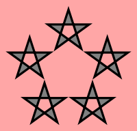
Example of multiple path commands and path operation loops. Example of geometric adjustments in loops and color adjustments in path commands:
startshape stars
background {sat 0.35}

path stars {
    MOVETO{x cos(90-144) y sin(90-144)}
    4* {r 144} LINETO {y 1}
    CLOSEPOLY{}
    5* {r 72} {
        FILL{y 1.88 b 0.5 p evenodd}
        STROKE{y 1.88}
    }
}
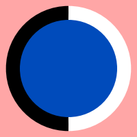
Example of optional MOVETOs and multiple sets of path sequences and commands:
path dot {
    MOVETO{y 1}        // required
    ARCTO{y -1 r 1}
    ARCTO{y 1 r 1}
    FILL{hue 216 sat 1 b 0.7333}
    MOVETO{y 1}        // can be left out
    ARCTO{y -1 r 1}
    STROKE{b -1 width 0.25}
    MOVETO{y -1}       // can be left out
    ARCTO{y 1 r 1}
    STROKE{b 1 width 0.25}
}
The second and third MOVETO operations are redundant. If they were left out then Context Free would automatically have generated them because all they do is move to the same position as the ARCTO operations that are at the end of the preceding path sequences.
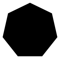
Example of implicit fill command:
path heptagon {
    MOVETO{x cos(90-360/7) y sin(90-360/7)}
    6* {r (360/7)} LINETO{y 1}
    CLOSEPOLY{}
}
The supported path operations are:
- MOVETO{x x1 y y1}
- Moves the path to the point (x1, y1) without drawing, begins a new path sequence
- LINETO{x x1 y y1}
- Draws a line to the point (x1, y1)
- ARCTO{x x1 y y1 rx x2 ry y2 r ellipse_angle param parameters}
- Draws an elliptical arc segment to the point (x1, y1), the ellipse has a radius (x2, y2) and is rotated by the ellipse angle (in degrees)
- ARCTO{x x1 y y1 r radius param parameters}
- Draws a circular arc segment with the specified radius to the point (x1, y1)
- CURVETO{x x_end y y_end x1 control_x_1 y1 control_y_1}
- Draws a quadratic bezier curve to point (x_end, y_end) with a control point at (control_x_1, control_y_1)
- CURVETO{x x_end y y_end x1 control_x_1 y1 control_y_1 x2 control_x_2 y2 control_y_2}
- Draws a cubic bezier curve to point (x_end, y_end) with a starting control point at (control_x_1, control_y_1) and an ending control point at (control_x_2, control_y_2)
- CURVETO{x x_end y y_end}
- Draws a smooth quadratic bezier curve to point (x_end, y_end) with a control point that is the mirror of the previous bezier curve †
- CURVETO{x x_end y y_end x2 control_x_2 y2 control_y_2}
- Draws a smooth cubic bezier curve to point (x_end, y_end) with a starting control point that is the mirror of the ending control point of the previous bezier curve and an ending control point at (control_x_2, control_y_2) †
It is not necessary to list all of the path operation parameters. If a path operation parameter is omitted then a default value will be used. The default position is (0,0) for end points and control points. If the x or y part of a position or control point is omitted then 0 will be used. However, for cubic bezier curves either x2 or y2 must be specified for Context Free to know that it is cubic and not quadratic. For non-smooth cubic and quadratic bezier curves either x1 or y1 must be specified for Context Free to know that the non-smooth variant is desired. For arcs, the default ellipse radius is (1,1) and the default angle is 0.
† The smooth forms of the quadratic and cubic curve operations infer the unspecified control point by looking at the preceding curve operation. If the preceding operation is not a curve operation (CURVETO, CURVEREL, ARCTO, or ARCREL) then a smooth curve operation is not permitted.
Each of the absolute path operations above has a relative form in which the position of the previous path operation is added to the current position (and to any control points):
- MOVEREL{x x1 y y1}
- Moves the path to the relative point (x1, y1) without drawing, begins a new path sequence
- LINEREL{x x1 y y1}
- Draws a line to the relative point (x1, y1)
- ARCREL{x x1 y y1 rx x_rad ry y_rad r ellipse_angle param parameters}
- Draws an elliptical arc segment to the relative point (x1, y1), the ellipse has a radius (x_rad, y_rad) and is rotated by the ellipse angle (in degrees)
- ARCREL{x x1 y y1 r radius param parameters}
- Draws a circular arc segment with the specified radius to the relative point (x1, y1)
- CURVEREL{x x_end y y_end x1 control_x_1 y1 control_y_1}
- Draws a quadratic bezier curve to relative point (x_end, y_end) with a relative control point at (control_x_1, control_y_1)
- CURVEREL{x x_end y y_end x1 control_x_1 y1 control_y_1 x2 control_x_2 y2 control_y_2}
- Draws a cubic bezier curve to relative point (x_end, y_end) with a starting relative control point at (control_x_1, control_y_1) and an ending relative control point at (control_x_2, control_y_2)
- CURVEREL{x x_end y y_end}
- Draws a smooth quadratic bezier curve to relative point (x_end, y_end) with a control point that is the mirror of the previous bezier curve †
- CURVEREL{x x_end y y_end x2 control_x_2 y2 control_y_2}
- Draws a smooth cubic bezier curve to relative point (x_end, y_end) with a starting control point that is the mirror of the ending control point of the previous bezier curve and an ending relative control point at (control_x_2, control_y_2) †
Path sequences can be explicitly ended and closed:
- CLOSEPOLY{param parameters}
- Ends the current polygon and draws a line from the ending position back to the beginning position, unless the beginning and end points coincide exactly. If the path sequence is stroked then the connected beginning and end are drawn with a line joint, rather than with two line end caps.
A path sequence is implicitly ended without closure by starting a new path sequence with MOVETO/MOVEREL, by following it with one or more path commands, or by ending the path.
path SomeOpenPathsAndAClosedPath {
    MOVETO{}
    LINEREL{y 1}
    LINEREL{x 1}
    MOVETO{x 1}        // ended previous path
    LINEREL{y 1}
    LINEREL{x 1}
    STROKE{}           // ended previous path sequence, strokes both open path sequences
    MOVETO{x 2}
    LINEREL{y 1}
    LINEREL{x 1}
}                      // ended last path sequence and fills it, which looks like a closed path
A design might have a series of drawing operations that should result in the last point being the same as the first point. But when the path is closed a small line segment might be seen at the join between the beginning and end points. This is due to floating point math errors causing the end point to be slightly off from the beginning point. There is an alternate form of CLOSEPOLY that modifies the last drawing point so that the end point exactly matches the beginning point:
- CLOSEPOLY{p align}
- Ends the current polygon and sets the ending point to exactly match the beginning point.
Context Free will scan backward until it finds a MOVETO or MOVEREL and sets the ending drawing operation to the same point as that MOVETO/MOVEREL.
After a path sequence there can be one or more path commands. Path commands instruct Context Free to draw (stroke or fill) all of the path sequences between the path command and the previous group of path commands.
- STROKE {shape adjustments width stroke_width param parameters}
- Stroke the preceding path sequences with a pen of the specified width. Stroke width is relative to the size of the shape. If the stroke size is not specified then the default of 0.1 is used. If color or shape modifications are specified then the path sequences are modified when they are drawn.
- FILL {shape adjustments param parameters}
- Fill the preceding path sequences. If color or shape modifications are specified then the path sequences are modified when they are drawn. If the path sequences are intersecting or self-intersecting then a filling rule determines whether a given piece is filled or not. The default filling rule is non-zero, but even-odd filling can also be specified (see below).
| Fill Parameter | Description | Examples |
|---|---|---|
| The default filling rule is non-zero | 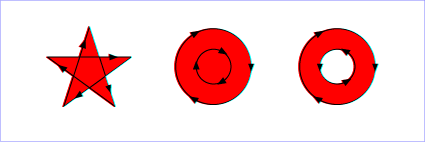 |
|
| evenodd | This parameter activates the even-odd filling rule | 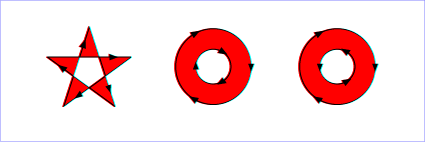 |
Note that the shape adjustments in path commands can either be basic or ordered (see basic vs. ordered).
If a path is completed (by a closing curly brace, '}') with no path command following the last set of path sequences then an implicit fill command is appended to the path.
Many path operations and commands have parameters that modify their action. These parameters have the form of the keyword 'p' or 'param' followed by a string. The string can be without quotes if it has no white-space characters. If there are white-space characters then the string must be enclosed in quotes.
| Operation/Command | Parameter | Description |
|---|---|---|
| ARCTO/ARCREL | cw | Indicates that the clock-wise arc is drawn. |
| ARCTO/ARCREL | large | Indicates that the large arc is drawn. |
| CLOSEPOLY | align | Indicates that the closing path operation should be modified to exactly match the beginning path position. |
| FILL | evenodd | Indicates that the even-odd filling rule is used. |
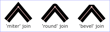
| STROKE | miterjoin | Indicates that join between path sequence segments (and between the beginning and end of closed paths) should have miter joins. |
| STROKE | roundjoin | Indicates that join between path sequence segments (and between the beginning and end of closed paths) should have round joins. |
| STROKE | beveljoin | Indicates that join between path sequence segments (and between the beginning and end of closed paths) should have bevel joins. |
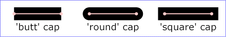
| STROKE | buttcap | Indicates that the end points of unclosed path sequences should have butt caps. |
| STROKE | roundcap | Indicates that the end points of unclosed path sequences should have round caps. |
| STROKE | squarecap | Indicates that the end points of unclosed path sequences should have square caps. |
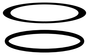
| STROKE | iso | Indicates that stroke width is not transformed if the stroke is transformed, short for isowidth. |
Default anisotropic stroke on top, isowidth on bottom.
The basic arc drawing operation specifies a start point, an end point, and an ellipse. The ellipse is positioned such that the start point and end points touch the ellipse and the arc is drawn from the start to the finish. However, in general there are two possible ellipse positions for any pair of starting and ending points, and two different arcs on each ellipse that can be drawn. The cw and large parameters indicate which of the four possible arcs are drawn.
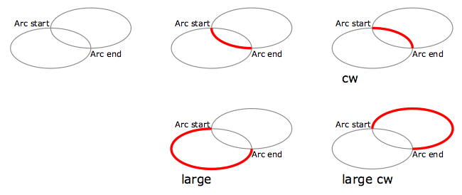
Two of the four arcs are large, i.e., more than 180°. Specifying the large parameter indicates that one of these arcs should be drawn. Otherwise one of the arcs that are less than 180° will be drawn. Two of the four arcs draw from start to end clockwise around the ellipse and two draw counter-clockwise. Specifying the cw parameter indicates that a clockwise arc should be drawn. Otherwise a counter-clockwise arc will be drawn.
Setting the radius of the arc to be negative has the effect of inverting the arc drawing direction. A counter-clockwise arc will be drawn clockwise if the radius is negative. A clockwise arc will be drawn counter-clockwise if the radius is negative.
The control points for bezier curve segments control the slope of the curve at the ends. For cubic bezier curves each end has its own control point and the slope at each end is indicated by the slope of the line from the end to the control point. For quadratic bezier curves both ends share a single control point and the slope at each end is indicated by the slope of the line from each end to the shared control point.
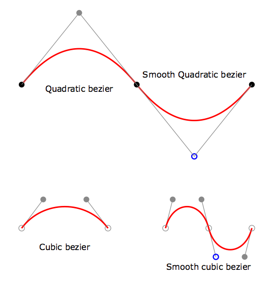
For smooth cubic bezier curves the starting control point is the mirror of the ending control point on the previous bezier curve or arc curve. For smooth quadratic bezier curves the single control point is the mirror of the ending control point on the previous bezier curve or arc curve. The preceding curve does not need to be of the same order (quadratic or cubic) as the smooth curve. The preceding curve can even be an ARCTO. Context Free will figure out what control point will match the slope and curvature between the smooth curve and the curve the precedes it.
Paths support the same extended loop constructs as rules, with a slight difference. Simple loops look pretty much the same as rule simple loops:
path trill {
    MOVETO {x cos(234) y sin(234)}
    5* {r -144}
        CURVETO {y 1 x1 (cos(234) + cos(324)) y1 (sin(234) + sin(324)) x2 1 y2 1}
    CLOSEPOLY {p align}
    5* {r 72}
        STROKE {y 2 p buttjoin a -0.5}
}
But for complex loops there is the restriction that loops must either be all path operations or all path commands, no mixing is allowed.
path suns {
    MOVETO{x 1}
    20* {r (360/20)} {
        LINETO{x (2*cos(360/40)) y (2*sin(360/40))}
        LINETO{x cos(360/20) y sin(360/20)}
    }
    CLOSEPOLY{p align}
    5* {r 72} {
        FILL{y 4}
        STROKE{y 4 b -0.1}
    }
}
Z changes are not allowed in the loop transform for path operation or command loops and color changes are not allowed in the loop transform for path operation loops.