-
Notifications
You must be signed in to change notification settings - Fork 1
1. First steps
Here is presented a quick demo of the Fraise system, in a few steps.
It assumes that you have at least one RaspberryPi Pico board.
First install Pure Data(Pd), you'll need a recent version (at least 0.54.1).
Run Pd, open the menu Help / Find externals, find and install the two externals Fraise and Fraise-toolchain.
Connect the Raspberry Pi Pico to your host computer using a micro-USB cable, making sure that you hold down the BOOTSEL button to force it into USB Mass Storage Mode. Once it is connected release the BOOTSEL button and it should automatically mount as a USB Mass Storage Device.
Drag-and-drop the file boards/pico/usb_bootloader.uf2 onto the mounted pico Mass Storage Device. The board will reboot, unmounting itself as a Mass Storage Device, and start to run the flashed code.
Now open the patch pico/fraise/example/blink.pd with Pd:

Normally, the pied/pied object should turn to yellow (as shown above), as well as the upper fruit/fruit.
The second fruit/fruit will remain gray (not detected).
The LED on the Pico board should start flashing, and moving the upper led period slider should change the flashing speed of the LED: the slider is connected to the message [c 1 c $1(, which sends a message to the Pico formed by a first byte of value "1" then a second byte of the slider's value.
Let's have a look to the source code of the current Pico's firmware, which is the file main.c located in the fw_blink sub-directory of the directory containing the patch (so the full path is pico/fraise/example/fw_blink/main.c). You can read from line 21:
void fraise_receivebytes(const char *data, uint8_t len){
    if(data[0] == 1) ledPeriod = (int)data[1] * 10;
    else (...)
}
That's how the Pico sets the flashing speed accordingly to the second byte of a 'bytes' message, if that message starts with a "1".
If you click on the upper [EHello( message (just under the led period slider), a text message is sent to the Pico. Because this text starts with a 'E', the Pico will return the same message to Pd (here 'E' stands for "Echo"). Check the Pd console: a new line should have been printed, saying:
from_fruit0: Ehello
allowing us to verify that bidirectional communication is established between the Pico and the Pd patch.
The explanation in the source code starts at line 30:
void fraise_receivechars(const char *data, uint8_t len){
    if(data[0] == 'E') { // Echo
        printf("E%s\n", data + 1);
    }
}Try making a few changes to main.c, for example change the following line in fraise_receivechars():
printf("E%s\n", data + 1);to
printf("Fruit received %s\n", data + 1);Save the main.c file, and follow the next steps:
- click the utils button on the
fruit/fruitobject, it will open this new window:

- in this new window, click the MAKE button. If your changes compile correctly, you should see the new RAM and ROM usage under the MAKE button. Otherwise check the Pd console to know which errors prevent your program to compile.
- now press the PROGRAM button. The program should start to upload to the Pico:

When the upload is finished, the Pico will reboot and execute your new program.
Now when you click on the [EHello(message, the console should print:
from_fruit0: Fruit received hello
Fraise makes adding one or more boards straightforward.
Note: we don't talk here about connecting another board to another USB port on the host computer. This is straightforward too, but will be explained later.
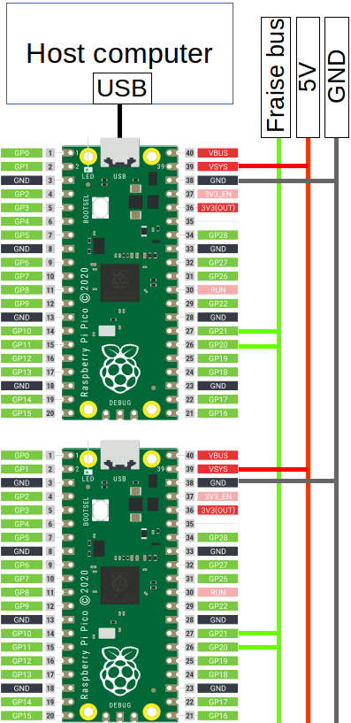
Here, we want to connect the second board to the first one, in order to share its USB connection. In the simplest case, we just have to connect GPIO 20 and 21 together, which forms the Fraise bus. All boards connected to the Fraise bus become visible and programmable from the Pd patch:

First, the second board must be programmed with the Fraise bootloader. Connect it via USB to the computer, in BOOTSEL mode, but this time drag-and-drop the file boards/pico/fraise_bootloader.uf2.
Short gpio 20 and 21, and connect them to the shorted gpio 20 and 21 of the first board, as shown before.
Now you should see both fruit/fruit objects turning to yellow: the second board is detected by the patch, known as the "fruit1" (like the USB bootloader, the Fraise bootloader integrates the "blink" demo so a freshly bootloaded board will be named "fruit1" and will start flashing).
Now the lower led period will change the flashing speed of the second board's LED, while the upper slider will continue to control the flashing speed of the first board.
Like with the first board, compilation and programming tasks are done via the fruit/fruit utils window:

You will notice that this windows has two more buttons than the first board's one, but let's ignore them for now.
You can recompile the firmware and send it to the board's flash memory in exactly the same way as for the first board.
That will be the case for any additional board (you will just have to rename them differently and to assign them another ID, see later).