Skip to content
New issue

Have a question about this project? Sign up for a free GitHub account to open an issue and contact its maintainers and the community.

By clicking “Sign up for GitHub”, you agree to our terms of service and privacy statement. We’ll occasionally send you account related emails.

Already on GitHub? Sign in to your account

Updated wiring instructions for Magic LED Controler ?? #231

Closed
xoseperez opened this issue Sep 28, 2017 · 9 comments
Closed

Updated wiring instructions for Magic LED Controler ?? #231

xoseperez opened this issue Sep 28, 2017 · 9 comments
Labels
enhancement New feature or request light major

Comments

@xoseperez
Copy link
Owner

Originally reported by: Vincèn PUJOL (Bitbucket: vincegre, GitHub: vincegre)


Hi

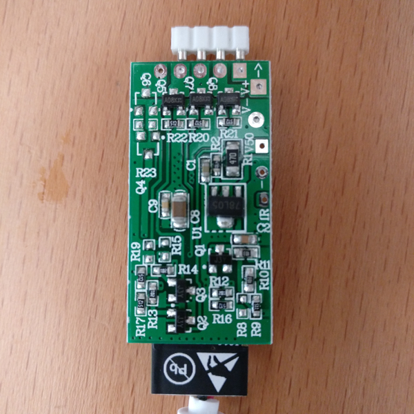
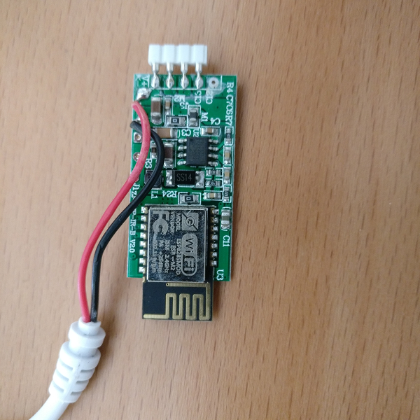
I was looking at Wiki to know how to wire my FTDI adapter on it but discovered mine doesn't have same board as the one in Wiki here: https://bitbucket.org/xoseperez/espurna/wiki/Hardware#markdown-header-magic-home-led-controller
Here are few pictures of it if it can help ??

Thanks!

case.png
top.png
bottom.png

@xoseperez
Copy link
Owner Author

Original comment by gimi87 (Bitbucket: gimi87, GitHub: gimi87):


I started this controller to work (2.0 PCB) and 1.4 version of PCB. Currently i am trying (since i'm discovering git repository) to create a pull request with the code changes and push the graphics with the description. If i will don't do this then i will send an email to the developer about the changes.

@xoseperez
Copy link
Owner Author

Original comment by Vincèn PUJOL (Bitbucket: vincegre, GitHub: vincegre):


Thanks a lot ;) Would you mind to share the graphics with description here in meantime ? or post an update here when Wiki is updated so I'm sure I don't miss it !!

@xoseperez
Copy link
Owner Author

Original comment by Vincèn PUJOL (Bitbucket: vincegre, GitHub: vincegre):


@gimi87 Some news about share of documents here or progress with developer ?

@xoseperez
Copy link
Owner Author

Original comment by Soif (Bitbucket: soif, GitHub: soif):


I've successfully flashed this v2.0 board !

While mine has an IR input, wiring must be the same because I've directly soldered to the ESP module (as you can see on the photo).

IMG_0357.JPG

Notice that with this board I had to change the GPI order in hardware.h :

#!arduino

    #define LIGHT_CH1_PIN       5     // RED
    #define LIGHT_CH2_PIN       12    // GREEN
    #define LIGHT_CH3_PIN       13    // BLUE

happy hacking

@xoseperez
Copy link
Owner Author

Original comment by gimi87 (Bitbucket: gimi87, GitHub: gimi87):


I'm so sorry for waiting. I was too busy. Yes this is the correct wiring to program the controller.
BUT... of course there is a few tricks to program:

  1. You need to connect 12V to the 2.1/5.5 white DC jack
  2. You need to bind GPIO0 to GND and then power up
  3. Connect Rx (board side) to the Tx of programmer, and of course Tx to Rx (cross rx/tx paths)
  4. Sometimes it will not program the board until you will reset the board again.

So my solution is to use a RST and GPIO0 pin attached to the "dedicated" programmer (like a Witty board or NodeMcu board) which can control additional pins.

I attached my code and some graphics with the pin description (and for 1.4 of PCB).

-> config/hardware.h

#!arduino

#elif defined(MAGICHOME_LED_CONTROLLER_2_0)

    // Info
    #define MANUFACTURER        "MAGICHOME"
    #define DEVICE              "LED_CONTROLLER_2_0"
    #define RELAY_PROVIDER      RELAY_PROVIDER_LIGHT
    #define LIGHT_PROVIDER      LIGHT_PROVIDER_DIMMER
    #define DUMMY_RELAY_COUNT   1

    // Channels
    #define LIGHT_CH1_PIN       5       // RED
    #define LIGHT_CH2_PIN       12     // GREEN
    #define LIGHT_CH3_PIN       13     // BLUE
    #define LIGHT_CH4_PIN       15     // WHITE

    #define LIGHT_CH1_INVERSE   0
    #define LIGHT_CH2_INVERSE   0
    #define LIGHT_CH3_INVERSE   0
    #define LIGHT_CH4_INVERSE   0

-> hardware.ino

#!arduino

#elif defined(MAGICHOME_LED_CONTROLLER_2_0)

        setSetting("board", 39);
        setSetting("relayProvider", RELAY_PROVIDER_LIGHT);
        setSetting("lightProvider", LIGHT_PROVIDER_DIMMER);
        setSetting("chGPIO", 1, 5);
        setSetting("chGPIO", 2, 12);
        setSetting("chGPIO", 3, 13);
        setSetting("chGPIO", 4, 15);
        setSetting("chLogic", 1, 0);
        setSetting("chLogic", 2, 0);
        setSetting("chLogic", 3, 0);
        setSetting("chLogic", 4, 0);
        setSetting("relays", 1);

-> platformio.ini

#!arduino

[env:magichome-led-controller-2-0]
platform = espressif8266
framework = arduino
board = esp01_1m
board_flash_mode = dout
lib_deps = ${common.lib_deps}
lib_ignore = ${common.lib_ignore}
build_flags = ${common.build_flags_1m} -DMAGICHOME_LED_CONTROLLER_2_0
monitor_baud = 115200

[env:magichome-led-controller-2-0-ota]
platform = espressif8266
framework = arduino
board = esp01_1m
board_flash_mode = dout
lib_deps = ${common.lib_deps}
lib_ignore = ${common.lib_ignore}
build_flags = ${common.build_flags_1m} -DMAGICHOME_LED_CONTROLLER_2_0
upload_port = "192.168.4.1"
upload_flags = --auth=fibonacci --port 8266
monitor_baud = 115200

IMG_20170906_180507.jpg
IMG_20170906_180616.jpg
IMG_20170906_180349.jpg
IMG_20170917_231417.jpg

@xoseperez
Copy link
Owner Author

Thank you very much, very detailed explanation.
Added your code to dev branch (901ffa7). Will release it soon.

@xoseperez
Copy link
Owner Author

Original comment by iLLiac4 (Bitbucket: iLLiac4, GitHub: iLLiac4):


Gret info tnx.
Xose Pérez: will you add this device also for Hyperion ambilight link you did with model 06?

TNX

@xoseperez
Copy link
Owner Author

Released with 1.9.6

@xoseperez
Copy link
Owner Author

Removing milestone: 1.9.6 (automated comment)

@xoseperez xoseperez added major light enhancement New feature or request labels Jan 24, 2018
Sign up for free to join this conversation on GitHub. Already have an account? Sign in to comment
Labels
enhancement New feature or request light major
Projects
None yet
Development

No branches or pull requests

1 participant