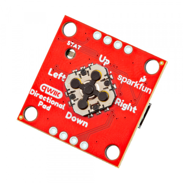
The SparkFun Qwiic Directional Pad adds a 5-way directional pad to your I2C bus! When connected to a microcontroller, press down on the directional pad (up, down, left, right, or center) to provide additional input for your application. The built-in RGB status LED provides visual feedback indicating which button is pressed.
---

<a href="https://www.sparkfun.com/products/26851">
  <b>SparkFun Qwiic Directional Pad</b>
  <br />
  PRT-26851
  <br />
  <center>[Purchase from SparkFun :fontawesome-solid-cart-plus:](https://www.sparkfun.com/products/26851){ .md-button .md-button--primary }</center>
</a>
In this tutorial, we'll go over the hardware and how to hookup the SparkFun Qwiic Directional Pad to an Arduino. We will also go over some Arduino examples to get started.
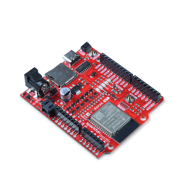
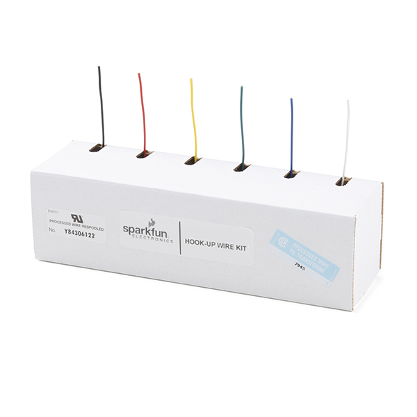
To follow along with this tutorial, you will need the following materials. You may not need everything though depending on what you have. Add it to your cart, read through the guide, and adjust the cart as necessary.
---

<a href="https://www.sparkfun.com/products/15424">
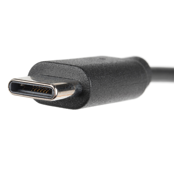
  <b>Reversible USB A to C Cable - 2m</b>
  <br />
  CAB-15424
</a>
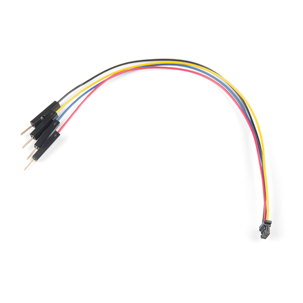
For those that want to take advantage of the Qwiic connector, you'll want to grab a Qwiic cable. There are a variety of other cable lengths available in the SparkFun catalog to choose from.
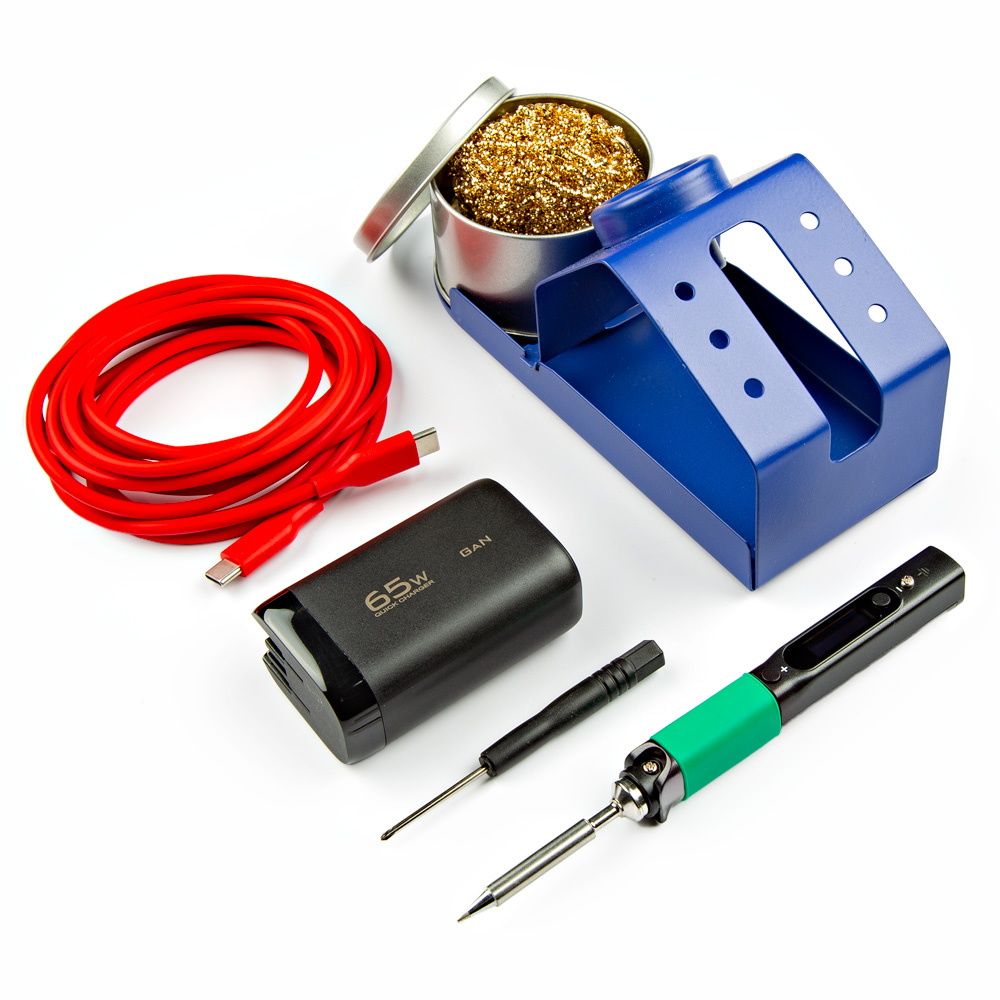
For users connecting to the plated through holes, you will need a soldering iron, solder, and general soldering accessories.
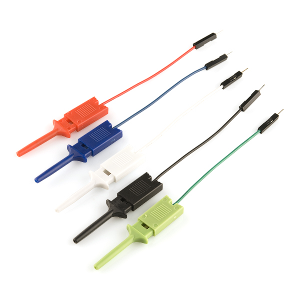
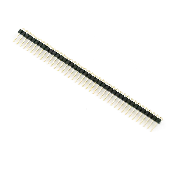
Depending on your setup, you may want to use IC hooks for a temporary connection. However, you will want to solder header pins to connect devices to the plated through holes for a secure connection.
If you aren't familiar with the Qwiic Connection System, we recommend reading here for an overview.
If you aren’t familiar with the following concepts, we also recommend checking out a few of these tutorials before continuing.
