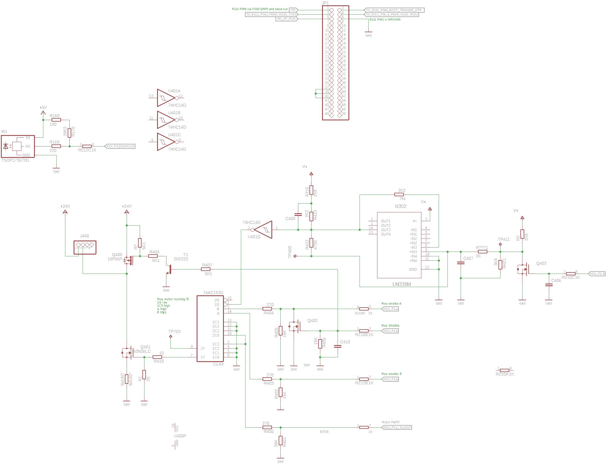
Reverse engineered schematic in Kicad for PCG5000G1 mainboard used in the Robomow RM-400/City-110/RM-510 lawn mower
I had been repairing a Robomow RM-510 lawn mower which mowing motor does not works. Test fails with error 55.
(In the case if you ran into the error 55 issue check the lid close checking Hall sensor...)
The same board is present in the RM-200 (at least it is possible to set it in the service menu)
The main focus of my work is the mowing motor driving circuit:
Later on I started to dream about integrating the robot into OpenMower.
Due to the limitations of the factry firmware at some point I would like to write a replacement firmware for it in Mowgli style.
IR receiver type is unknown the following is present on it's back:
3
8   K
   O S
    C
-
MCU is clocked from a 16 MHz crystal
-
IR remote receiver IC OC output is connected to the MCU's P2.5 pin (INPC15)
-
Timer1 used for measuring time interupts on the INPC15
-
Timer1 has 160 prescaler -> 1 timer increment == 10 us 100 kHz-n jár
-
Timer1 CH5 set to measure time on both edges (
MOV.B #3, g1tmcr5 ; CH5 on IR input measure both edges) -
Upon IC interrupt:
- The timer value (G1TM5) stored
- The time difference from the last impulse lenght is calculated (current width - prev width)
- Check if the current is longer than 4560 us + the previous
-
Timer1 overflow interrupt generated when the 15th bit overflows (G1BCR0 IT set to 0)
-
Timer1 overflow has a timeout counter variable which incremented in the overflows 2 times
- timer_counter_1,2, ir_timeout_counter counts 0-1-2 (after 0ms - 655,35ms - 1310,7ms)
