- Pulse Width Modulation
- Led Dimmer
- PWM – For controlling speed
- Motor Drivers
- Description Of Functions Used
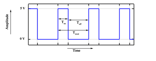
Pulse Width Modulation (PWM) is a square wave with varying low and high amplitude signal. A general PWM signal is given in a figure below:
There are various terms related with the Pulse Width Modulation:-
- Off-Time :- Duration of time period when the signal is low.
- ON-Time :- Duration of time period when the signal is high.
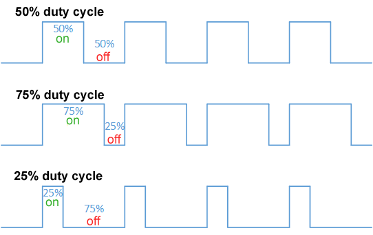
- Duty cycle :- It is the percentage of the time period when the signal remains ON during the period of the pulse width modulation signal.
- Period :- It is the sum of off-time and on-time of pulse width modulation signal.
Calculation of duty cycle is done by calculating the ON-time from total period of time. It is a ratio between ON-time and total time period of the signal using period calculation, duty cycle is calculated as shown in the equation below:
As represented in the above figure, Toff represents the off-time and Ton represents the on-time of a signal. Period is a sum of both on and off times and period is calculated as shown in the equation below:
PWM signals when operates at different duty cycle it gives a varying voltage at the output. Voltage regulation method is used in various areas of application like:
- Audio
- LED dimmers
- Analog Signal Generation
- Switching regulators
- Motor Control
Voltage regulation operation is performed by averaging the PWM signal. Output voltage is calculated as shown in the equation below:
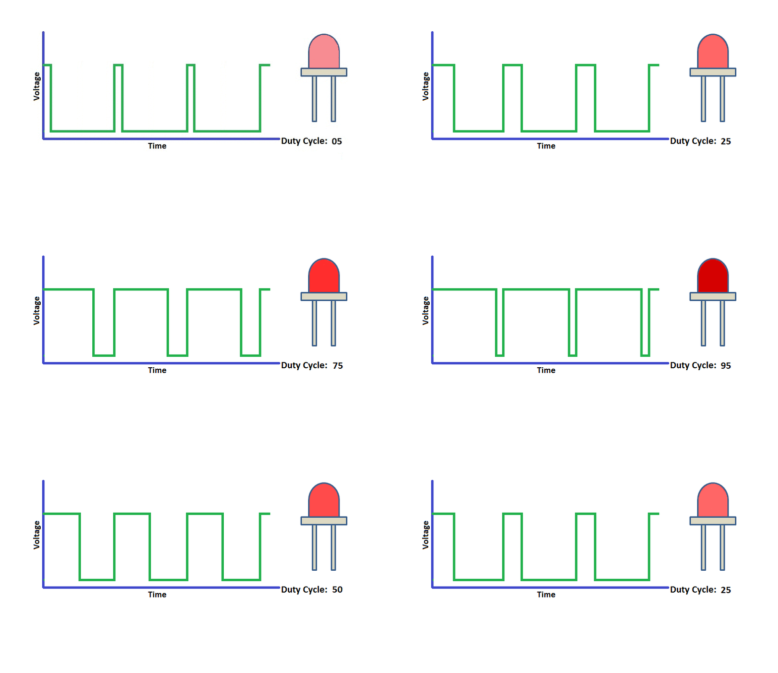
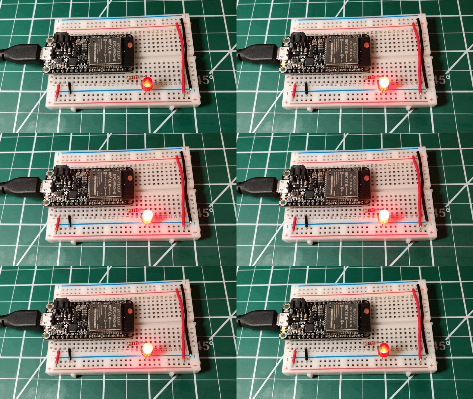
- LED Dimmer is the best example to visualise the working of the PWM
- PWM technique (pulse width modulation) is a very efficient way of controlling the brightness of LEDs with minimum energy waste. I
- Instead of varying the brightness by varying the supply current with a variable resistor or transistor it is accomplished by varying the ratio of ON time vs OFF time. This saves the lot of energy.
-
The speed of a DC motor can be controlled by varying its input voltage, i.e. by using PWM.The higher the duty cycle, the greater the average voltage being applied to the dc motor(High Speed) and the lower the duty cycle, the less the average voltage being applied to the dc motor(Low Speed).
-
To control the speed of a d.c. motor we need a variable voltage d.c. power source. However if you take a 12v motor and switch on the power to it, the motor will start to speed up: motors do not respond immediately so it will take a small time to reach full speed. If we switch the power off sometime before the motor reaches full speed, then the motor will start to slow down. If we switch the power on and off quickly enough, the motor will run at some speed part way between zero and full speed. This is exactly what a p.w.m. controller does: it switches the motor on in a series of pulses. To control the motor speed it varies (modulates) the width of the pulses – hence Pulse Width Modulation.
Motor drivers acts as an interface between the motors and the control circuits. Motor require high amount of current whereas the controller circuit works on low current signals. So the function of motor drivers is to take a low-current control signal and then turn it into a higher-current signal that can drive a motor.
The motor driver we will use in this workshop is TB6612FNG Motor driver
-
esp_err_t enable_motor_driver_a(int mode)
Description : Enables Motor driver A in Parallel or Normal Mode.
Parameters :
mode: if mode = 1 is passed, motor driver is operated in parallel mode, if mode = 2 is passed, motor driver is operated in normal mode
Returns : esp_err_t returns ESP_OK if motor driver initialised properly, else it returns ESP_ERR_INVALID_ARG
-
esp_err_t enable_motor_driver_b(int mode)
Description : Enables Motor driver B in Parallel or Normal Mode.
Parameters :
mode: if mode = 1 is passed, motor driver is operated in parallel mode, if mode = 2 is passed, motor driver is operated in normal mode
Returns : esp_err_t returns ESP_OK if motor driver initialised properly, else it returns ESP_ERR_INVALID_ARG
-
  esp_err_t set_motor_speed (int 	motor_id,
                             int 	direction,
                             float duty_cycle )
Description : Set the speed of motors.
Parameters :
-
motor_id: set it as MOTOR_A_0, MOTOR_A_1, MOTOR_B_0, MOTOR_B_1 to select the appropriate motor to set its speed and direction -
direction: set is as MOTOR_FORWARD for forward motion, MOTOR_BACKWARD for backward motion, MOTOR_STOP to stop the motor -
duty_cycle: set the duty cycle of the motor driver PWM
Returns : esp_err_t returns ESP_OK if speed correctly, ESP_FAIL if any error occurs
-
-
void vTaskDelay(const TickType_t xTicksToDelay)
Description : Delay a task for a given number of ticks.The constant portTICK_PERIOD_MS can be used to calculate real time from the tick rate - with the resolution of one tick period.
Parameters :
xTicksToDelay: The amount of time, in tick periods, that the calling task should block.
-
  static BaseType_t xTaskCreate(TaskFunction_t pvTaskCode,
                                const char *constpcName,
                                const uint32_t usStackDepth,
                                void *constpvParameters,
                                UBaseType_t uxPriority,
                                TaskHandle_t *constpvCreatedTask)
Description : Create a new task and add it to the list of tasks that are ready to run.
Parameters :
-
pvTaskCode: Pointer to the task entry function. Tasks must be implemented to never return (i.e. continuous loop), or should be terminated using vTaskDelete function. -
pcName: A descriptive name for the task. This is mainly used to facilitate debugging. Max length defined by configMAX_TASK_NAME_LEN - default is 16. -
usStackDepth: The size of the task stack specified as the number of bytes. Note that this differs from vanilla FreeRTOS. -
pvParameters: Pointer that will be used as the parameter for the task being created. -
uxPriority: The priority at which the task should run. Systems that include MPU support can optionally create tasks in a privileged (system) mode by setting bit portPRIVILEGE_BIT of the priority parameter. For example, to create a privileged task at priority 2 the uxPriority parameter should be set to ( 2 | portPRIVILEGE_BIT ). -
pvCreatedTask: Used to pass back a handle by which the created task can be referenced.
Returns : pdPASS if the task was successfully created and added to a ready list, otherwise an error code defined in the file projdefs.h
-


