There are a number of sources available on how to use the scaling tool in OpenSim GUI; however, the guidance available is very generic because the process of scaling is highly subjective. Therefore, here, we outline the important steps, tips and shortcuts that can be performed to successfully scale a model to a desired outcome.
We structured the document into three sections, namely:
- Pre-scaling: what is required and what to look out for?
- Scaling: what is required and what to look out for?
- Post-scaling: assessment of a scaled model, what is required and what to look out for?
Please note that the scaling methodology below is based on the current version of OpenSim 4.0 and OpenSim 4.1.
Scaling is changing the size of a generic model to a more personalised model. Generic models are built based on cadavers. A generic model can have one or multiple parts of the body, for example a model can have one upper limb with the thorax and scapula. Scaling generic models is important to output a more representative or subject-specific result.
If you are scaling a model using marker data only, then you need to carry out the following steps to prepare the necessary files.
A. Trc files to input in OpenSim Scale tool
Marker data collected from a Vicon-like system in a biomechanics lab are stored in a binary file format called C3D file. Currently, C3D files cannot be read directly in the OpenSim GUI, they need to be converted to other file types such as .trc and .mot files (please note that .mot file is not relevant to the scaling of a model). A TRC file is a tab-separated-values text format (similar to “TVS”) and can therefore be opened with spreadsheet software (Excel, LibreOfficeCalc, …) to change the marker labels, or add or remove values. In addition, marker data collected in biomechanics labs could have different coordinate systems and marker labels compared to the OpenSim generic model. Therefore, the initial step is to convert the C3D file into an appropriate file format before commencing with the transformation and label matching.
There are a number of ways to read C3D files and correct marker labels, one is to use Mokka. This software allows you to save your C3D file as different file formats including .trc, and you can also manipulate the marker labels and also create average markers. Mokka is a graphical interface for the Biomechanical Toolkit which has API for C++, Matlab and Python (https://biomechanical-toolkit.github.io/). OpenSim, since version 4.0, also uses BTK to convert and manipulate C3D and trc files. It is accessible from the opensim API (C++, Matlab and Python) but not directly in the OpenSim GUI. To use OpenSim’s MATLAB API, there is an example script called ‘c3dExport.m’ which usually comes with the OpenSim software and you can find it in OpenSim’s script folder (C:...\Documents\OpenSim\4.1\Code\Matlab). Several proprietary software from the Motion Capture Systems also allow exporting in a trc compatible format, instead of C3D (Qualisys, ?Vicon). A web front-end for BTK is available at http://tools.noventas.org
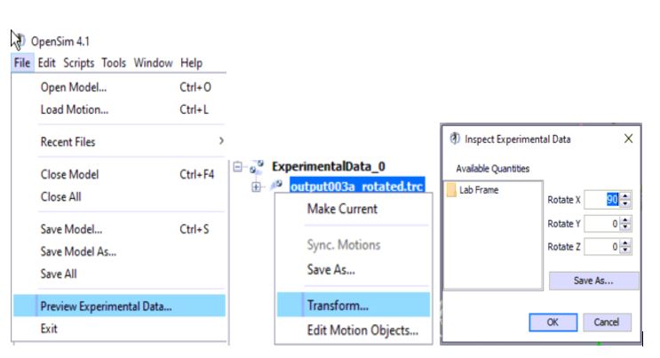
B. Coordinate Systems
Opensim uses the standard engineering coordinate system of X forward (Red), Y up (Green), Z right (Blue). Most motion capture systems use different laboratory coordinates (X forward, Y left, Z up) and require a 90 degree rotation about the X axis, that can be performed in OpenSim GUI:
 .
.
C. In the OpenSim model file, define which markers placement are the most accurate (i.e. anatomical markers, joint centers, virtual markers) by defining them as “fixed”: This way, they will not be moved during the scaling process.
Other markers that are not defined as “fixed” (i.e. cluster markers or other experimental markers which location on each segment can vary from session to session) will be moved on the scaled model during the process to match the placement of the experimental ones.
 .
.
D. Create the virtual markers needed to define each segment in three axis
• See video webinar
• Take screenshots
• Show mokka + matlab + python option to generate averaged marker for joint center (e.g. elbow), show online option
• Provide example of calculation of a joint center marker from a) dynamic movement trials and b) regression equation
How to scale a model?
There are three ways to scale a model when using the scaling tool in OpenSim, you can scale using:
• Marker data
• Manual scaling
• Mix of markers and manual scaling
For all the three approaches above, you need to decide which marker pairs on the generic model you want to use on each segment in order to scale.
For that reason, your generic model should have and usually do have a relevant marker set.
If you are scaling a model using manual scaling approach only, then you need to carry out the following steps to prepare the necessary information:
During manual scaling, estimated scale factors are needed for each segment that you want to scale.
The confusing thing to look out for is that just because you are manually scaling a generic model does not mean you are free from using marker pairs.
Unfortunately, you still have to decide which marker pairs you need in order to scale the model uniformly or non-uniformly.
Manual scaling uniformly means the segments in the generic model will be scaled in x, y, and z directions equally by the same amount.
For example, if the scale factor of 0.5 is applied uniformly on ‘thorax’, the result will show that thorax is halved equally in x, y and z directions.
Non-uniform scaling is recommended during the manual scaling, this allows models to be scaled differently in different directions.
If you are scaling a model using both manual scaling and marker data approach, then you need to carry out the following steps to prepare the necessary information:
 .
.
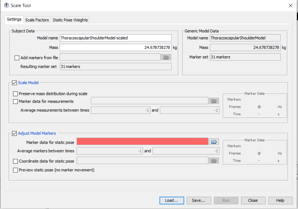
This figure shows scale tool which consists of three tabs: ‘Settings’, ‘Scale Factors’, and ‘Static Pose Weights’.
The Settings tab:
• The box on the upper left, Subject Data, defines the scaled model’s name, mass and model marker file (usually the models already consist of a marker set, and this option adds an additional marker set to the model).
IMPORTANT NOTE: Here, the mass is NOT the total mass of a subject, but instead it is the mass of the model.
For example, if your model only has one lower limb, then the mass should reflect that (read the discussion below for more details on mass distribution).
• The box on the upper right, Generic Model Data, outlines the generic model’s name, mass, and marker set number. These information are embedded in the generic model (.osim) file and you cannot modify them in this window.
• Scale Model box is linked to the “scale factors tab”
• Adjust Model Markers box:
This option should be ticked in most situations. It a) moves the model in the subject’s position by performing a small IK task, and b) performs “marker registration” which moves the markers of the model (that are not designed as “fixed”) to match those of the trc file.
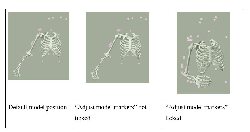
a. Calculation of the static pose:
The model will keep its default “pose” (joint angles) if the “adjust model markers” is not ticked.
Example:
 .
.
Default model position “Adjust model markers” not ticked “Adjust model markers” ticked.
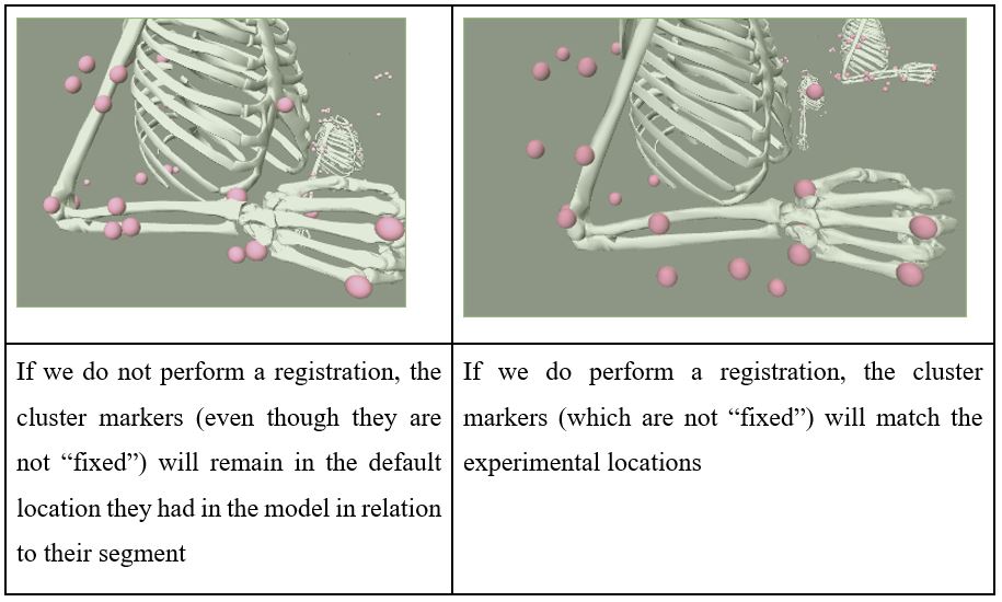
b. Marker registration
Marker registration moves the markers of the model (that are not designed as “fixed”) to match those of the trc file.
Example:
 .
.
If we do not perform a registration, the cluster markers (even though they are not “fixed”) will remain in the default location they had in the model in relation to their segment If we do perform a registration, the cluster markers (which are not “fixed”) will match the experimental locations.
“Preview static pose” option is disregarded in opensim 4x, and we should use “Preview Experimental data” to compare/overlay the model markers and experimental markers: see issue/comment, does not seem to work with opensim >3.3.
The Scale Factors tab: • Check videos • Mid-point marker required for all 3 axis, link to tools/tutos/code to do this easily • Example config file with screenshots
The Static Pose Weights tab: • ...
How is mass scaled in the OpenSim model?
We found out that the mass input into the model during the scaling process should be relevant to the segments that exist in the model.
For example, you cannot add a total mass of a person in a model while the model only consists of the torso and one arm because OpenSim thinks the mass you added is for the existing segments.
Hence, the correct way to do this is to estimate mass for the existing segments in the model, and this is tricky to do very accurately.
There are some generic solutions:
• There is a paper by Dempster & Gaughran (1967) and they try to generalize mass distribution across the body based on total body mass.
This can be used as a way to estimate the relevant weight that needs to be added to the model.
Table 4 and Table 6 are relevant.
However, this paper used cadavers with limited representations.
Link to paper: https://people.unica.it/brunoleban/files/2013/10/Dempster-AJA1967-Properties-od-body-segments-based-on-size-and-weight.pdf
• Alternatively, you can derive a rough ratio based on a model.
For example, Ajay's shoulder model had a participant with total mass of 52kg, and in their model they have added 24.6787kg in their model.
So, 24.6787/51 gives roughly 0.47459.
Hence, if for example a mass of a person is 80kg, then the mass that needs to be added into AJ’s model during scaling will be 80*0.47459=37.9672kg.