🤗 Please consider subscribing to my YouTube channel Your subscription goes a long way in backing my work.
ESPBell-LITE and ESPBell-MAX
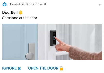
ESPBell-LITE "IoT Intercom / Doorbell" module enables you to stay informed whenever someone rings your doorbell or presses the intercom button. Upon receiving an interactive notification, you have the convenience to either promptly open the door or choose to dismiss the alert by simply tapping the button within the notification. See the screenshot below.
Currently supported Home Assistant and ESPHome If I have time I'll add control by Telegram and WhatsApp
Note
If you're ready to contribute to the project, your support would be greatly appreciated. Due to time constraints, I may not be able to quickly verify new "features" or completely new "code" functionality. Therefore, please refrain from making changes to the original code. Instead, create a new code/script in the 'Contributors_code' folder and use this README_Contributors.md Thank you very much!
- YouTube video How To
- My Shop
- Aliexpress
- Pogo pin Clamp 6Pin 2.54mm spacing
- Power Supply 5V 0.6A or any 5V power supply you have
- Based on ESP12F "Programmable via pads on the PCB"
- Input / Output
- 1 x "LOCK" Solid State Relay "SSR" 2.4A 30v Max
- 1 x "BELL" Input Optocoupler 2-30v AC/DC Max "For Doorbell"
- 1 x "ADC" Input 1v Max
- 3 x GPIO "12,13,14" 3.3v DC MAX
- 1 x GND
- 1 x 5V DC "Input"
- Status LEDs
- 1 x DoorBell
- 1 x On ESP module "Not used"
- Button for flashing Firmware
Note
Requires 5V 0.3A+ DC power supply.
Note
✅ Please check your Intercom type. It needs to be a 5-wire intercom system. I hope that everything is crystal clear as I've made every effort to provide a step-by-step explanation of the setup process. If you have any further questions regarding the setup or require assistance with assembling a printed circuit board, feel free to join our Facebook Group or open a new discussion topic in the dedicated tab.
Important
If you're new to ESP-related matters, please refrain from asking basic questions like "how to program ESP8266". There are already plenty of excellent tutorials available on the internet. If you encounter any issues, remember that providing detailed information about the problem will help me offer more effective assistance. More information equals better help!
Warning
I would strongly advise against attempting to assemble this PCB or buy it from my shop if you have no experience "0%" in soldering, or working with ESP / ESPHome / Arduino boards. Connecting ESPBell-LITE to your intercom or doorbell demands a certain level of electronics expertise and the proficiency to utilize a multimeter effectively. Please be aware that I cannot assume responsibility for any errors or issues that may arise. My role is to provide guidance and advice to the best of my abilities.
This project is open-source, allowing you to assemble ESPBell-LITE on your own. To simplify this process, I've provided an "Interactive HTML Boom File" located in the PCB folder. This interactive file helps you identify where to solder each component and polarity, reducing the chances of errors to a minimum. But if you don't feel confident in assembling it yourself, you can always opt to purchase a pre-assembled board from my Shop
The beauty of ESPHome is in its simplicity, you just need to change one config the "Delay" time. After you click open in the notification it will keep the relay engaged until the delay has elapsed.
# Door Lock Opener "Momentary Switch" Keeps SSR ON for 1.5s.
  - platform: gpio
    pin: 5
    id: Lock
    name: "Lock"
    icon: "mdi:lock"
    restore_mode: ALWAYS_OFF
    on_turn_on:
    - delay: 1500ms
    - switch.turn_off: Lock
Full yaml
substitutions:
  name: ESPBell-LITE

esphome:
  name: espbell-lite
  name_add_mac_suffix: false
  project:
    name: pricelesstoolkit.espbell-lite
    version: "1.0"

esp8266:
  board: esp12e


dashboard_import:
  package_import_url: github://PricelessToolkit/ESPBell-LITE/Code/ESPHome/espbell-lite.yaml@main
  import_full_config: true

# Enable logging
logger:

# Enable Home Assistant API
api:
  encryption:
    key: "Eg3Bw0WXj3ShNV3sN11dfOj+0UmBdF7irFaCnDnZpXk="

ota:
  password: "54699445e0aab07e709ffadssd188eb0"
  # For boards after around 2024-10-01:
  #password: "password"

wifi:
  ssid: !secret wifi_ssid
  password: !secret wifi_password
  fast_connect: true

  # Enable fallback hotspot (captive portal) in case wifi connection fails
  ap:
    ssid: "${name} Fallback Hotspot"
    password: "password"

captive_portal:

sensor:

- platform: uptime
  name: "${name}"
  id: uptime_seconds

- platform: wifi_signal
  name: "${name} WiFi Signal"

binary_sensor:

# Doorbell Sensor
  - platform: gpio
    pin:
      number: 4
      #inverted: true
    name: "DoorBell"
    icon: "mdi:bell"
    filters:
      delayed_on: 100ms

  - platform: status
    name: "${name} Status"

switch:

# Door Lock Opener "Momentary Switch" Keeps SSR ON for 1.5s.
  - platform: gpio
    pin: 5
    id: Lock
    name: "Lock"
    icon: "mdi:lock"
    restore_mode: ALWAYS_OFF
    on_turn_on:
    - delay: 1500ms
    - switch.turn_off: Lock

  - platform: restart
name: ${name} restartNote
Ready-made boards already come with ESPHome firmware flashed, so you probably don't need to reprogram it via USB.
Just connect to the Hotspot ESPBell-LITE Fallback Hotspot through your mobile phone, the default password is password, and fill in your Wi-Fi Access Point credentials. After that notification will pop up in the ESPHome control panel, which will allow you to import the full configuration automatically. If this does not work you need to upload the firmware via USB-TTL.
To upload the firmware into ESPBell-LITE you will need two things.
- Regular USB-TTL 3.3v adapter. I have open-source USB-TTL project, in case you don’t have a TTL adapter yet and want to assemble it yourself.
- Pogo pin Clamp Fixture single row 6 Pin 2.54mm spacing or you can solder wires directly to ESPBell-LITE for programming.
| USB-TTL | ESPBell-LITE |
|---|---|
| TX | RX |
| RX | TX |
| GND | GND |
| 3.3v | 3.3V |
Here is a multi-user configuration example, which means that a notification is sent to several family members. If one family member clicks on the notification, the notification disappears from the other phones. For all this to work we need to create "three" automation, but before that, in this example, you need to change a minimum few things.
- Image file path or snapshot from the camera that is used as a background for notification (mutually exclusive).
- The name of the mobile device that is connected to the Home Assistant. In my case, it's "doogee_v20pro" and "Second_Phone"
- Entity id
  image: /media/local/notify/doorbell.jpg
  image: /api/camera_proxy/camera.name
- service: notify.mobile_app_doogee_v20pro
- service: notify.mobile_app_Second_Phone
- entity_id: switch.espbell_lite_lock
This automation sends an interactive notification with the "tag: intercom" to phones.
Explanation click here
Alias: This is a user-defined name or label for the automation. In this case, it's given the name "🔔 Intercom DoorBell Notification," which suggests that it's related to receiving notifications for an intercom or doorbell event.Description: This field is left empty, so there's no additional description provided for this automation.
Trigger: The trigger specifies the event or condition that will start the automation. In this case, it is triggered when the state of the "binary_sensor.espbell_lite_doorbell" changes to "on." This implies that the automation will run when the binary sensor named "binary_sensor.espbell_lite_doorbell" switches from an off state to an on state.
Condition: There are no additional conditions specified. This means the automation will proceed without any additional conditions beyond the trigger.
Action: The action section defines what should happen when the trigger condition is met. In this case, there are two actions defined:
The first action uses the "notify.mobile_app_doogee_v20pro" service to send a notification to a mobile device. The notification includes a message "Someone at the door" and is configured with various data attributes, including a persistent notification, high importance, a specified channel ("intercom"), and a tag ("intercom"). It also includes an image file path or camera snapshot for the notification and two actions that can be taken by the recipient: "Ignore ✖" and "Open The Door 🔓".
The second action is similar to the first but uses the "notify.mobile_app_Second_Phone" service to send the same notification to another mobile device.
Mode: The mode is set to "single," which means that the automation will only run once for each trigger event. Subsequent trigger events will not cause the automation to run again until the current execution has been completed.
alias: 🔔 Intercom DoorBell Notification
description: ""
trigger:
  - platform: state
    entity_id:
      - binary_sensor.espbell_lite_doorbell
    to: "on"
condition: []
action:
  - service: notify.mobile_app_doogee_v20pro
    data:
      data:
        persistent: true
        importance: high
        channel: intercom
        tag: intercom
        #Use this to add a snapshot of a camera
        image: /api/camera_proxy/camera.name
        #or this for a static image (mutually exclusive)
        image: /media/local/notify/doorbell.jpg
        actions:
          - action: intercom_ignore
            title: Ignore ✖
          - action: intercom_open
            title: Open The Door 🔓
      title: DoorBell 🔔
      message: Someone at the door
  - service: notify.mobile_app_Second_Phone
    data:
      data:
        persistent: true
        importance: high
        channel: intercom
        tag: intercom
        #Use this to add a snapshot of a camera
        image: /api/camera_proxy/camera.name
        #or this for a static image (mutually exclusive)
        image: /media/local/notify/doorbell.jpg
        actions:
          - action: intercom_ignore
            title: Ignore ✖
          - action: intercom_open
            title: Open The Door 🔓
      title: DoorBell 🔔
      message: Someone at the door
mode: single
This automation clears notifications with the "tag: intercom" on phones when an ignore button on the notification is pressed.
Explanation click here
Alias: The alias is a user-defined name or label for the automation, and in this case, it's named "🔔 Intercom DoorBell ignore notification Dismiss." This name suggests that the automation is related to dismissing or ignoring notifications for an intercom or doorbell event.Description: The description field is left empty, so there's no additional description provided for this automation.
Trigger: This automation is triggered by an event. The trigger condition is defined as follows:
platform: The trigger platform is "event," which means the automation will be triggered by an event.
event_data: The automation will only trigger when the event data contains a specific action. In this case, the trigger event is looking for events with the action "intercom_ignore."
event_type: The automation is tied to the "mobile_app_notification_action" event type. It implies that this automation is designed to respond to actions taken by the user within a mobile app notification.
Condition: There are no additional conditions specified. This means the automation will proceed without any additional conditions beyond the trigger.
Action: The action section specifies what should happen when the trigger condition is met. This automation has two actions:
The first action uses the "notify.mobile_app_doogee_v20pro" service to send a notification with the message "clear_notification." It also includes data attributes with the "tag" set to "intercom." This effectively clears or dismisses the notification with the "intercom" tag on the "mobile_app_doogee_v20pro" mobile app.
The second action is identical to the first but uses the "notify.mobile_app_Second_Phone" service to clear or dismiss the notification on another mobile device with the "intercom" tag.
Mode: The mode is set to "single," which means that the automation will only run once for each trigger event. Subsequent trigger events with the "intercom_ignore" action will trigger this automation, but it will only clear the notification once.
alias: 🔔 Intercom DoorBell ignore notification Dismiss
description: ""
trigger:
  - platform: event
    event_data:
      action: intercom_ignore
    event_type: mobile_app_notification_action
condition: []
action:
  - service: notify.mobile_app_doogee_v20pro
    data:
      message: clear_notification
      data:
        tag: intercom
  - service: notify.mobile_app_Second_Phone
    data:
      message: clear_notification
      data:
        tag: intercom
mode: singleThis automatization enables the Relay and clears notifications with the "tag: intercom" on phones when the notification button is pressed on one of the phones.
alias: 🔔 intercom open the door and Dismiss notification
description: ""
trigger:
  - platform: event
    event_data:
      action: intercom_open
    event_type: mobile_app_notification_action
condition: []
action:
  - service: notify.mobile_app_oneplus_a5010
    data:
      message: clear_notification
      data:
        tag: intercom
  - service: notify.mobile_app_oneplus8t
    data:
      message: clear_notification
      data:
        tag: intercom
  - service: switch.toggle
    data: {}
    target:
      entity_id: switch.espbell_lite_lock
mode: single
Warning
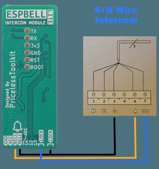
The cable colors do not follow the conventional scheme. Red is not VCC (5V); instead, black is the 5V line! Please refer to the silkscreen on the device for the correct connections.
Differences Between 4+N and 1+N Intercom Systems. Click here
In the world of intercom systems, two common configurations stand out: 4+N and 1+N. Understanding the distinctions between these setups is crucial for successful installation and operation. Here's a quick overview:
4+N Intercom Systems:
In a 4+N system, the "4" signifies the presence of four distinct wires, each with a specific purpose. These four wires are typically allocated as follows: one for the microphone, one for the speaker, one for the doorbell, and one for the lock. Additionally, the "N" wire represents the neutral wire, which is used for the electrical current's return path. 4+N systems offer separate wiring and control for microphone, speaker, doorbell, and lock functions.
1+N Intercom Systems:
In contrast, a 1+N system streamlines the wiring process by combining audio communication and power supply over a single wire. The "1" in 1+N indicates that one wire is used for both audio communication and power transmission. Like 4+N systems, the "N" wire in 1+N systems also stands for the neutral wire. 1+N systems simplify wiring, using a single wire for audio and power, making installation more straightforward.
Note
Currently, only the 4+N Intercom system is supported by ESPBell-LITE. But if you want you can connect ESPBell-LITE to the unsupported intercom buttons directly!
Warning
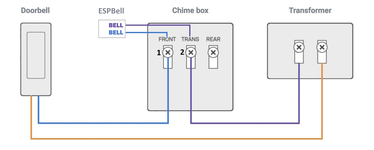
If there is current leakage between contacts 1 and 2 see "Dorbell wiring diagram" ESPBell-LITE may trigger randomly "The current flow may be due to the installed light bulb in the doorbell button which illuminates all the time" So before you start it’s better to check it with a multimeter.
Experiencing WiFi disconnections with ESPBell-LITE? This usually indicates WiFi network issues.
Try these steps for a more stable connection:
- Update Firmware: Ensure both ESPHome and ESPBell are updated.
- Check WiFi Environment: Use a WiFi analyzer to avoid crowded channels and ensure strong signal strength.
- Disable WiFi Power Saving: set "power_save_mode: none" in your ESPHome code. "only helps in some cases, in other it can make things worse"
- Disable Bandwidth Steering: Prevents automatic switching between 2.4GHz and 5GHz bands.
- Set Channel Bandwidth to 20MHz: This can improve stability in crowded WiFi areas.
- Use a Fixed WiFi Channel: Avoids interruptions from automatic channel changes.
- Use a Fixed IP Address.
- Official ESPHome workarounds https://esphome.io/guides/faq.html#my-node-keeps-reconnecting-randomly
💡 Verify the maximum number of devices your WIFI Access Point can support. Different Access Points have varying limits for connected devices. The best practice is to use a separate access point for IoT devices for enhanced performance and security.


